beautypg.com
Manuals
Brands
GE Manuals
Medical Equipment
Lullaby Warmer
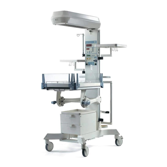
GE Lullaby Warmer Manuals
Manuals and User Guides for GE Lullaby Warmer. We have
1
GE Lullaby Warmer manual available for free PDF download: Maintenance And Service Manual
GE Lullaby Warmer Maintenance And Service Manual (165 pages)
Brand:
GE
| Category:
Medical Equipment
| Size: 6.79 MB
Table of Contents
Table of Contents
13
Important Safety Information
21
Warnings, Cautions and Notes
21
Symbols
23
About this Manual
26
Scope and Intended Users
26
Organization of this Manual
26
Chapter 1 Introduction
27
Indications for Use (Intended Use)
27
Figure 1: Lullaby TM Warmer
27
Mechanical Controls and Cable Connections
28
Figure 2: Front Oblique View
28
Figure 3: Front View
28
Figure 4: Side View
29
Figure 5: Back View
29
Controls and Displays
30
Figure 6: Controls and Displays
30
Figure 7: Temperature Settings and Modes
30
Figure 8: Alarms and Indications
31
Figure 9: APGAR
31
Control Modes and Indication
32
Figure 10: Manual Mode
32
Figure 11: Baby Mode
33
Displays
34
Figure 12: Displays
34
Switches and Keys
35
Figure 13: Keys
35
Figure 14: Power Standby/On Switch
36
Figure 15: Power Standby/On Switch
36
Alarms and Indication
37
Figure 16: Alarms
37
Figure 17: Global Alarm
38
Figure 18: Check Baby Alarm
38
Figure 19: Probe Failure Indicator
39
Figure 20: System/ Heater Failure Alarms
40
Figure 21: OVR
41
Figure 22: UVR
41
Figure 23: Heat off Indicator
41
Chapter 2 System Setup and Checkout Procedures
42
2.1 Mechanical Checks
42
Figure 24: Power Failure Indicator
42
Figure 25: Disconnecting the Power Cord
43
Figure 26: Power Cord
43
Figure 27: Inspecting the Lullaby
43
Figure 28: Locking/Releasing Rear Caster Brakes
44
Figure 29: Inspecting the Bedside Panel
44
Figure 30: Inspecting the Bedside Panel Lock
44
Figure 31: Tilting the Bed Towards the Pillar
45
Figure 32: Tilting the Bed Away from the Pillar
45
Figure 33: Bed Position Parallel to Floor
45
Figure 34: Hood Swivel - Right
45
Figure 35: Hood Swivel - Left
45
Figure 36: Hood Lock
45
2.2 Controller Checks
46
Figure 37: Power Connection
46
Figure 38: Patient Probe Connection
46
Figure 39: Power Standby/On Switch
46
2.3 Accessories Check
47
Figure 40: Checking the Skin Probe
47
Figure 41: Checking the Accessories
47
Figure 42: Opening the Drawer
47
Chapter 3 Maintenance and Cleaning
48
3.1 Repair Policy
48
3.2 Required Tools and Personnel Protection Equipment
48
Maintenance Schedule
48
Operator Maintenance
49
3.4 Cleaning Instructions
49
Figure 43: the Hood
50
Cleaning the Lullaby Tm Warmer
51
Figure 44: Removing the Plexiglas
51
Figure 45: Removing the Mattress
51
Figure 46: Removing the Plexiglas
52
Figure 47: Cleaning with Ear Bud
52
Figure 48: Removing the X-Ray Tray
52
3.6 Cleaning Solutions
53
3.7 Cleaning and Disinfecting Individual Components
53
3.8 Cleaning Other Components
54
Chapter 4 Troubleshooting
55
Chapter 5 System Installation Procedure
62
Required Tools and Personnel Protection Equipment (Ppe)
62
Contents of Lullaby Tm Warmer Packaging
62
Unpacking the Shipping Box
64
Figure 49: Unpacking the Lullaby
64
Figure 50: Contents of Lullaby
65
Figure 51: Contents of Lullaby
65
Pillar to Leg Assembly and Height Adjustment
66
Figure 52: Pillar Assembly
66
Figure 53: Leg Assembly
67
Figure 54: the Location of the Screw Holes on the Leg Assembly
68
Figure 55: Pillar to Leg Assembly
68
Assembly of Pillar and Bed
70
Figure 56: Bed Base Assembly
70
Figure 57: Bedside Panels Assembly
71
Figure 58: Mattress, Clear Plexiglas Plate, and X-Tray Tray Assembly
71
Figure 59: Pillar and Bed Assembly
71
Assembling the Pillar and the Hood
72
Figure 60: the Pillar and the Hood
72
Figure 61: Printed Circuit Board Wire Assembly (PWA)
74
Connecting the Power Cord
75
Mounting the Accessories
75
Figure 62: Basic Warmer
75
Figure 63: Mounting the IV Pole
76
Mounting the IV Pole
76
Figure 64: the Monitor Tray Assembly
77
Figure 65: Assembling the Monitor/Instrument Tray
77
Figure 66: Mounting the Utility Pole
77
Mounting the Monitor /Instrument Tray
77
Mounting the Utility Pole
77
Figure 67: Setting the Rear Castor Brakes
78
Figure 68: Setting the Rear Castor Brakes
78
Figure 69: the Cylinder Holder
78
Figure 70: Fastening with Velcro
78
Figure 71: Mounting Bracket
78
Figure 72: Mounting Cylinder
78
Mounting the Cylinder Holder and the Cylinder
78
Figure 73: Mounting the Drawer Assembly
79
Mounting the Drawer Assembly
79
Figure 74: Mounting the Chest Tube Drainage Hanger
80
Figure 75: Mounting the Tubing Management Arm
80
Mounting the Chest Tube Drainage Hanger
80
Mounting the Tubing Management Arm
80
5.8.10 Mounting the Resuscitation Bag Clip
81
Figure 76: Mounting the Utility Pole
81
Figure 77: Mounting the Basket Assembly
81
Figure 78: Mounting the Resuscitation Bag Clip
81
Mounting the Basket Assembly
81
Mounting the Utility Post (3.5")
81
5.8.11 Mounting the Retaining Clip
82
5.8.12 Assembling the Slotted Bedside Panel
82
Checkout Procedures
82
Figure 79: Mounting the Resuscitation Bag Clip
82
Figure 80: Assembling the Slotted Bedside Panel
82
Repacking the Warmer Without Skd for Local Transport
83
Chapter 6 System Dismantling Procedure
84
Dismantling the Accessories
84
Dismantling the Base and Bed
84
Dismantling the Hood Assembly
85
Dismantling the Pillar to Leg Assembly
86
Chapter 7 Field Replaceable Unit (Fru) Replacement Procedures
87
Replacing the Parts of the Lullaby
87
Tm Warmer
87
Replacing the Hood Exterior (FRU Kit No: 2043936-001)
87
Figure 81: the Heater Hood with the Components Separated
87
Replacing the Extrusions
88
Figure 82: Replacing the Rear Brackets and the Extrusions
88
Replacing the Hood Spacer, Hood Top Plate and Observation Lamp Plate
89
Figure 83: Replacing Hood Spacer, Top Plate, Observation Lamp Plate and Extrusions
89
Replacing the Front Bracket
90
Figure 84: Bracket and Extrusions
90
Replacing the Front and Rear Covers
91
Figure 85: Replacing Rear Covers
91
Replacing the PCB Wire Assembly (PWA) (FRU Kit No. 2043951-001)
92
Figure 86: Replacing Lullaby
92
Replacing the Hood Support Plate and Rear Bracket (FRU KIT: 2043937-001)
97
Replacing the Heater Assembly (FRU Kit No. 2043938-001) and Heater Cables
101
Figure 87: Replacing Heater Assembly
101
Replacing the Heater Assembly
105
001For 115V and 2061250-001 for 100V ) and Heater Cables (Part of FRU Kit No. 2062276- 001 for 230V, 2062276-001 for 115V and 2062276-001 for 100V)
105
Figure 88: Replacing Heater Assembly
105
Replacing the Heater Tube (FRU Kit No. 2045962-001)
108
Figure 89: Rear View of the Heater Assembly
108
Figure 90: Front View of the Heater Assembly
108
Replacing the Observation Lamp (FRU Kit No. 2043939-001)
109
Figure 91: Replacing the Observation Lamp
109
Replacing the LED Observation Lamp (FRU Kit No. 2062275-001)
110
Figure 92: Replacing the Observation Lamp
110
Figure 93: Replacing UI Sticker
111
Replacing the Bed Tilt Mechanism (FRU Kit No. 2043943-001)
112
Replacing the Bed Base Assembly (FRU Kit No. 2043949-001)
117
Replacing the Front and Rear Covers of Height Skirt (Part of FRU Kit No. 2043952-001)
117
Replacing the Castors (FRU Kit No. 2043945-001) and Leg Cap
117
Figure 94: Replacing Castors and Leg Cap
117
Replacing the Mattress (FRU Kit No. 2045963-001), Clear Plexiglas Plate (FRU Kit No. 2043946-001) and X-Ray Tray (FRU Kit No. 2043947-001)
118
Replacing the Bedside Panel (FRU Kit No. 2043948-001)
118
Figure 95: Lowering the Bedside Panel
118
Figure 96: Removing the Bedside Panel
118
Figure 97: Replacing the Bedside Panel
118
7.1.20 Replacing the Plate Power Inlet
119
Figure 98: Replacing the Plate Power Inlet
119
Replacing the Pillar Rear Cover (Part of FRU Kit No. 2043952-001)
120
Replacing the Cable Harness FRU (FRU Kit No. 2043950-001)
120
Figure 99: Replacing the Cable Harness
120
Replacing the Cable Harness FRU (FRU Kit No. 2062276-001 for 230V, 115V and for 100V)
121
Figure 100: Replacing the Cable Harness
121
Replacing the SMPS FRU (2062282-001)
122
Figure 101: Replacing the SMPS
122
Chapter 8 Fru Parts
123
Chapter 9 Illustrated Parts
132
9.1 Electrical Wiring Diagram
132
Figure 102: Electrical Wiring Diagram
133
9.2 Block Diagram
134
Figure 103: Block Diagram
135
9.3 Hood Assembly
136
Figure 104: Hood Assembly
136
Figure 105: Hood Assembly
136
Figure 106: Hood Assembly
137
Figure 107: Hood Assembly
137
Base Assembly
141
Figure 108: Base Assembly
141
Figure 109: Base Assembly
142
Figure 110: Base Assembly
143
Figure 111: Base Assembly
144
9.5 Bed Assembly
147
Figure 112: Bed Assembly
147
Chapter 10 Product Labels
148
Appendix A
152
Temperature Conversion Chart
152
Appendix B
153
Power Requirements
153
Standards
153
Classification
153
Operating Environment
154
Storage and Transport Conditions
154
User Control Settings
154
Performance
154
Mechanical Specifications
155
Weight Bearing Capacity
155
Appendix C
156
Electromagnetic Compatibility
156
Appendix D - Conforming to Standards and Directives
160
Appendix E - Assembling and Dismantling the Msb Drawer Assembly
161
Figure 113: Mounting the Drawer Assembly with Base Leg Cover
161
Figure 114: Latch Operation in Slider
161
Figure 115: Mounting the Drawer Assembly with the Drawer Clamp
162
Figure 116: Mounting the Drawer Assembly with Base Leg Cover
163
Related Products
GE LOGIQ 7
GE Lemage SX
GE Lemage SX/E
GE LOGIQ F Series
GE LOGIQ S6
GE LOGIQ 3
GE LOGIQworks Workstation
GE LOGIQ E8
GE LOGIQ P5 Basic OB
GE LOGIQworks
GE Categories
Refrigerator
Ranges
Microwave Oven
Air Conditioner
Dishwasher
More GE Manuals