beautypg.com
Manuals
Brands
GE Manuals
Control Unit
MiCOM P40 Agile
GE MiCOM P40 Agile Manuals
Manuals and User Guides for GE MiCOM P40 Agile. We have
8
GE MiCOM P40 Agile manuals available for free PDF download: Technical Manual
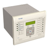
GE MiCOM P40 Agile Technical Manual (962 pages)
P446SV
Brand:
GE
| Category:
Relays
| Size: 31.94 MB
Table of Contents
Table of Contents
3
Chapter 1 Introduction
33
Figure 197: Circuit Breaker Fail Logic - Part
33
Circuit Breaker Fail Logic - Part
34
Aided Scheme
34
Rear Serial Port
34
Figure 198: Circuit Breaker Fail Logic - Part
34
Figure 250: TCS Scheme
34
Chapter Overview
35
Circuit Breaker Fail Logic - Part
35
Cip
35
Figure 199: Circuit Breaker Fail Logic - Part
35
Foreword
36
Target Audience
36
Typographical Conventions
36
Cip
36
Nomenclature
37
Compliance
37
Cip
37
Product Scope
38
Product Versions
38
Cip
38
Ordering Options
39
Figure 1: P40L Family - Version Evolution
39
Figure 145: Autoreclose System Map - Part
39
Features and Functions
40
Distance Protection Functions
40
Protection Functions
40
Figure 146: Autoreclose System Map - Part
40
Control Functions
41
Measurement Functions
41
Communication Functions
41
Figure 147: Autoreclose System Map - Part
41
Logic Diagrams
43
Figure 2: Key to Logic Diagrams
44
Functional Overview
45
Figure 3: Functional Overview
45
Chapter 2 Safety Information
47
Chapter Overview
49
Health and Safety
50
Symbols
51
Installation, Commissioning and Servicing
52
Lifting Hazards
52
Electrical Hazards
52
UL/CSA/CUL Requirements
53
Fusing Requirements
53
Equipment Connections
54
Protection Class 1 Equipment Requirements
54
Pre-Energisation Checklist
55
Peripheral Circuitry
55
Upgrading/Servicing
56
Decommissioning and Disposal
57
Regulatory Compliance
58
EMC Compliance: 2014/30/EU
58
LVD Compliance: 2014/35/EU
58
R&TTE Compliance: 2014/53/EU
58
UL/CUL Compliance
58
ATEX Compliance: 2014/34/EU
58
Chapter 3 Hardware Design
61
Chapter Overview
63
Hardware Architecture
64
Figure 4: Hardware Architecture
64
Mechanical Implementation
65
Housing Variants
65
Figure 5: Exploded View of IED
65
List of Boards
66
Front Panel
67
40TE Front Panel
67
Front Panel Compartments
67
Figure 6: Front Panel (40TE)
67
Keypad
68
Front Serial Port (SK1)
68
Front Parallel Port (SK2)
69
Fixed Function Leds
69
Programable Leds
69
Rear Panel
70
Figure 7: Rear View of Populated Case
70
Boards and Modules
71
Pcbs
71
Figure 8: Rear Connection to Terminal Block
71
Main Processor Board
72
Figure 9: Main Processor Board
72
Power Supply Board
73
Figure 10: Power Supply Board
73
Figure 11: Power Supply Assembly
74
Watchdog
75
Figure 12: Power Supply Terminals
75
Rear Serial Port
76
Figure 13: Watchdog Contact Terminals
76
Figure 14: Rear Serial Port Terminals
77
Figure 15: IEC 61850-9-2LE Board
77
IEC61850-9-2LE Ethernet Board
77
Standard Output Relay Board
78
Figure 16: Standard Output Relay Board - 8 Contacts
78
IRIG-B Board
79
Figure 17: IRIG-B Board
79
Fibre Optic Board
80
Figure 18: Fibre Optic Board
80
Rear Communication Board
81
Ethernet Board
81
Figure 19: Rear Communication Board
81
Figure 20: Ethernet Board
81
Redundant Ethernet Board
83
Figure 21: Redundant Ethernet Board
83
Coprocessor Board
85
Coprocessor Board with 1PPS Input
85
Figure 22: Fully Populated Coprocessor Board
85
High Break Output Relay Board
86
Figure 23: High Break Relay Output Board
86
Figure 24: High Break Contact Operation
87
Chapter 4 Software Design
89
Chapter Overview
91
Sofware Design Overview
92
Figure 25: Software Architecture
92
System Level Software
93
Real Time Operating System
93
System Services Software
93
Self-Diagnostic Software
93
Startup Self-Testing
93
System Boot
93
System Level Software Initialisation
94
Platform Software Initialisation and Monitoring
94
Continuous Self-Testing
94
Platform Software
96
Record Logging
96
Settings Database
96
Interfaces
96
Protection and Control Functions
97
Acquisition of Samples
97
Frequency Tracking
97
Direct Use of Sample Values
97
Distance Protection
97
Fourier Signal Processing
98
Figure 26: Frequency Response of FIR Filters
98
Programmable Scheme Logic
99
Event Recording
99
Figure 27: Frequency Response (Indicative Only)
99
Disturbance Recorder
100
Fault Locator
100
Function Key Interface
100
Chapter 5 Configuration
101
Chapter Overview
103
Settings Application Software
104
Using the HMI Panel
105
Navigating the HMI Panel
106
Getting Started
106
Figure 28: Navigating the HMI
106
Default Display
107
Default Display Navigation
108
Figure 29: Default Display Navigation
108
Password Entry
109
Processing Alarms and Records
110
Menu Structure
110
Changing the Settings
111
Direct Access (the Hotkey Menu)
112
Setting Group Selection Using Hotkeys
112
Control Inputs
113
Circuit Breaker Control
113
Function Keys
114
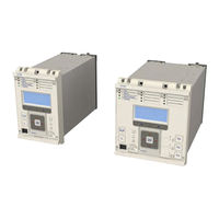
GE MiCOM P40 Agile Technical Manual (668 pages)
Feeder Management IED
Brand:
GE
| Category:
Control Unit
| Size: 21.79 MB
Table of Contents
Table of Contents
3
Chapter 1 Introduction
27
Rear Serial Port
28
Chapter Overview
29
Trip Circuit Supervision Scheme
29
Cip
29
Foreword
30
Target Audience
30
Typographical Conventions
30
Cip
30
Nomenclature
31
Cip
31
Product Scope
32
Ordering Options
32
Cip
32
Features and Functions
33
Protection Functions
33
Control Functions
34
Measurement Functions
34
Communication Functions
34
Compliance
36
Functional Overview
37
Figure 1: Functional Overview
37
Chapter 2 Safety Information
39
Chapter Overview
41
Health and Safety
42
Symbols
43
Installation, Commissioning and Servicing
44
Lifting Hazards
44
Electrical Hazards
44
UL/CSA/CUL Requirements
45
Fusing Requirements
45
Equipment Connections
46
Protection Class 1 Equipment Requirements
46
Pre-Energisation Checklist
47
Peripheral Circuitry
47
Upgrading/Servicing
48
Decommissioning and Disposal
49
Regulatory Compliance
50
EMC Compliance: 2014/30/EU
50
LVD Compliance: 2014/35/EU
50
R&TTE Compliance: 2014/53/EU
50
UL/CUL Compliance
50
ATEX Compliance: 2014/34/EU
50
Chapter 3 Hardware Design
53
Chapter Overview
55
Hardware Architecture
56
Figure 2: Hardware Architecture
56
Mechanical Implementation
57
Housing Variants
57
Figure 3: Exploded View of IED
57
List of Boards
58
Front Panel
59
Front Panel Compartments
59
Figure 4: Front Panel (60TE)
59
HMI Panel
60
Front Serial Port (SK1)
60
Figure 5: HMI Panel
60
Front Parallel Port (SK2)
61
Fixed Function Leds
61
Function Keys
61
Programable Leds
62
Rear Panel
63
Figure 6: Rear View of Populated Case
63
Figure 7: Terminal Block Types
64
Boards and Modules
65
Pcbs
65
Subassemblies
65
Figure 8: Rear Connection to Terminal Block
65
Main Processor Board
66
Figure 9: Main Processor Board
66
Power Supply Board
67
Figure 10: Power Supply Board
67
Figure 11: Power Supply Assembly
68
Watchdog
69
Figure 12: Power Supply Terminals
69
Rear Serial Port
70
Figure 13: Watchdog Contact Terminals
70
Input Module - 1 Transformer Board
71
Figure 14: Rear Serial Port Terminals
71
Figure 15: Input Module - 1 Transformer Board
71
Input Module Circuit Description
72
Figure 16: Input Module Schematic
72
Transformer Board
73
Figure 17: Transformer Board
73
Input Board
74
Figure 18: Input Board
74
Standard Output Relay Board
75
Figure 19: Standard Output Relay Board - 8 Contacts
75
IRIG-B Board
76
Figure 20: IRIG-B Board
76
Fibre Optic Board
77
Figure 21: Fibre Optic Board
77
Rear Communication Board
78
Ethernet Board
78
Figure 22: Rear Communication Board
78
Figure 23: Ethernet Board
78
Redundant Ethernet Board
80
Figure 24: Redundant Ethernet Board
80
Chapter 4 Software Design
83
Chapter Overview
85
Sofware Design Overview
86
Figure 25: Software Architecture
86
System Level Software
87
Real Time Operating System
87
System Services Software
87
Self-Diagnostic Software
87
Startup Self-Testing
87
System Boot
87
System Level Software Initialisation
88
Platform Software Initialisation and Monitoring
88
Continuous Self-Testing
88
Platform Software
89
Record Logging
89
Settings Database
89
Interfaces
89
Protection and Control Functions
90
Acquisition of Samples
90
Frequency Tracking
90
Direct Use of Sample Values
90
Fourier Signal Processing
90
Programmable Scheme Logic
91
Figure 26: Frequency Response (Indicative Only)
91
Event Recording
92
Disturbance Recorder
92
Fault Locator
92
Function Key Interface
92
Chapter 5 Configuration
93
Chapter Overview
95
Settings Application Software
96
Using the HMI Panel
97
Navigating the HMI Panel
98
Getting Started
98
Figure 27: Navigating the HMI
98
Default Display
99
Default Display Navigation
100
Figure 28: Default Display Navigation
100
Password Entry
101
Processing Alarms and Records
101
Menu Structure
102
Changing the Settings
103
Direct Access (the Hotkey Menu)
104
Setting Group Selection Using Hotkeys
104
Control Inputs
104
Circuit Breaker Control
105
Function Keys
105
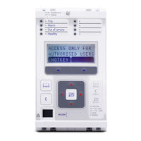
GE MiCOM P40 Agile Technical Manual (802 pages)
Single Breaker Current Differential (with Distance)
Brand:
GE
| Category:
Control Unit
| Size: 43.94 MB
Table of Contents
Table of Contents
3
Table of Figures
27
Chapter 1 Introduction
37
Section 3
39
Chapter Overview
39
Foreword
40
Target Audience
40
Typographical Conventions
40
Compliance
41
Nomenclature
41
Product Scope
42
Product Versions
42
Figure 1: P40L Version M85 - Version Evolution
43
Ordering Options
43
Current Differential Protection Functions
44
Distance Protection Functions
44
Features and Functions
44
Protection Functions
44
Control Functions
45
Communication Functions
46
Measurement Functions
46
Logic Diagrams
47
Figure 2: Key to Logic Diagrams
48
Figure 3: Functional Overview
49
Functional Overview
49
Chapter 2 Safety Information
51
Chapter Overview
53
Health and Safety
54
Symbols
55
Installation, Commissioning and Servicing
56
Lifting Hazards
56
Electrical Hazards
56
UL/CSA/CUL Requirements
57
Fusing Requirements
57
Equipment Connections
58
Protection Class 1 Equipment Requirements
58
Pre-Energisation Checklist
59
Peripheral Circuitry
59
Upgrading/Servicing
60
Decommissioning and Disposal
61
Regulatory Compliance
62
EMC Compliance: 2014/30/EU
62
LVD Compliance: 2014/35/EU
62
R&TTE Compliance: 2014/53/EU
62
UL/CUL Compliance
62
ATEX Compliance: 2014/34/EU
62
Chapter 3 Hardware Design
65
Section 4
67
Chapter Overview
67
Coprocessor Hardware Architecture
68
Figure 4: Hardware Architecture
68
Hardware Architecture
68
Figure 5: Coprocessor Hardware Architecture
69
Figure 6: Exploded View of IED
70
Housing Variants
70
Mechanical Implementation
70
List of Boards
71
Figure 7: Front Panel (60TE)
73
Front Panel
73
Front Panel Compartments
73
Front Serial Port (SK1)
74
Keypad
74
Fixed Function Leds
75
Front Parallel Port (SK2)
75
Function Keys
75
Programable Leds
76
Figure 8: Rear View of Populated Case
77
Rear Panel
77
Figure 9: Terminal Block Types
78
Boards and Modules
79
Figure 10: Rear Connection to Terminal Block
79
Pcbs
79
Subassemblies
79
Figure 11: Main Processor Board
80
Main Processor Board
80
Figure 12: Power Supply Board
81
Power Supply Board
81
Figure 13: Power Supply Assembly
82
Figure 14: Power Supply Terminals
83
Watchdog
83
Figure 15: Watchdog Contact Terminals
84
Rear Serial Port
84
Figure 16: Rear Serial Port Terminals
85
Figure 17: Input Module - 1 Transformer Board
85
Input Module - 1 Transformer Board
85
Figure 18: Input Module Schematic
86
Input Module Circuit Description
86
Figure 19: Transformer Board
87
Transformer Board
87
Figure 20: Input Board
88
Input Board
88
Figure 21: Standard Output Relay Board - 8 Contacts
89
Standard Output Relay Board
89
Figure 22: IRIG-B Board
90
IRIG-B Board
90
Fibre Optic Board
91
Figure 23: Fibre Optic Board
91
Ethernet Board
92
Figure 24: Rear Communication Board
92
Figure 25: Ethernet Board
92
Rear Communication Board
92
Figure 26: Redundant Ethernet Board
94
Redundant Ethernet Board
94
Coprocessor Board
96
Coprocessor Board with 1PPS Input
96
Current Differential Inputs
96
Figure 27: Fully Populated Coprocessor Board
96
Chapter 4 Software Design
99
GE MiCOM P40 Agile Technical Manual (554 pages)
Brand:
GE
| Category:
Control Unit
| Size: 19.49 MB
Table of Contents
Table of Contents
3
Chapter 1 Introduction
27
Rear Serial Port
28
Figure 171: TCS Scheme
28
Chapter Overview
29
Foreword
30
Target Audience
30
Typographical Conventions
30
Cip
30
Nomenclature
31
Compliance
31
Cip
31
Product Scope
32
Ordering Options
32
Cip
32
Features and Functions
33
Protection Functions
33
Cip
33
Control Functions
34
Measurement Functions
35
Communication Functions
35
Logic Diagrams
36
Figure 1: Key to Logic Diagrams
36
Functional Overview
37
Figure 2: Functional Overview
37
Chapter 2 Safety Information
39
Chapter Overview
41
Health and Safety
42
Symbols
43
Installation, Commissioning and Servicing
44
Lifting Hazards
44
Electrical Hazards
44
UL/CSA/CUL Requirements
45
Fusing Requirements
45
Equipment Connections
46
Protection Class 1 Equipment Requirements
46
Pre-Energisation Checklist
47
Peripheral Circuitry
47
Upgrading/Servicing
48
Decommissioning and Disposal
49
Regulatory Compliance
50
EMC Compliance: 2014/30/EU
50
LVD Compliance: 2014/35/EU
50
R&TTE Compliance: 2014/53/EU
50
UL/CUL Compliance
50
ATEX Compliance: 2014/34/EU
50
Chapter 3 Hardware Design
53
Chapter Overview
55
Hardware Architecture
56
Memory and Real Time Clock
56
Figure 3: Hardware Design Overview
56
Mechanical Implementation
57
Housing Variants
57
Figure 4: Exploded View of IED
57
20TE Rear Panel
58
Figure 5: 20TE Rear Panel
58
Figure 6: 30TE Three-MIDOS Block Rear Panel
59
Figure 7: 30TE Two-MIDOS Block + Communications Rear Panel
59
Figure 8: 30TE Two-MIDOS Block + Blanking Plate
60
Terminal Connections
61
I/O Options
61
Front Panel
62
20TE Front Panel
62
Figure 9: Front Panel (20TE)
62
30TE Front Panel
63
Keypad
63
Figure 10: Front Panel (30TE)
63
Liquid Crystal Display
64
USB Port
64
Fixed Function Leds
65
Function Keys
65
Programable Leds
65
Chapter 4 Software Design
67
Chapter Overview
69
Software Design Overview
70
Figure 11: Software Structure
70
System Level Software
71
Real Time Operating System
71
System Services Software
71
Self-Diagnostic Software
71
Startup Self-Testing
71
System Boot
71
System Level Software Initialisation
72
Platform Software Initialisation and Monitoring
72
Continuous Self-Testing
72
Platform Software
73
Record Logging
73
Settings Database
73
Interfaces
73
Protection and Control Functions
74
Acquisition of Samples
74
Frequency Tracking
74
Fourier Signal Processing
74
Programmable Scheme Logic
75
Event Recording
75
Figure 12: Frequency Response (Indicative Only)
75
Disturbance Recorder
76
Fault Locator
76
Function Key Interface
76
Chapter 5 Configuration
77
Chapter Overview
79
Settings Application Software
80
Using the HMI Panel
81
Navigating the HMI Panel
82
Getting Started
82
Figure 13: Navigating the HMI
82
Default Display
83
Default Display Navigation
84
Figure 14: Default Display Navigation
84
Password Entry
85
Processing Alarms and Records
85
Menu Structure
86
Changing the Settings
87
Direct Access (the Hotkey Menu)
88
Setting Group Selection Using Hotkeys
88
Control Inputs
88
Circuit Breaker Control
89
Function Keys
89
Date and Time Configuration
91
Time Zone Compensation
91
Daylight Saving Time Compensation
91
Settings Group Selection
92
Chapter 6 Current Protection Functions
93
Chapter Overview
95
Overcurrent Protection Principles
96
IDMT Characteristics
96
IEC 60255 IDMT Curves
97
European Standards
99
Figure 15: IEC 60255 IDMT Curves
99
North American Standards
100
IEC and IEEE Inverse Curves
102
Figure 16: IEC Standard and very Inverse Curves
102
Figure 17: IEC Extremely Inverse and IEEE Moderate Inverse Curves
102
Differences between the North American and European Standards
103
Programmable Curves
103
Principles of Implementation
103
Figure 18: IEEE very and Extremely Inverse Curves
103
Timer Hold Facility
104
Figure 19: Principle of Protection Function Implementation
104
GE MiCOM P40 Agile Technical Manual (600 pages)
Motor Protection IED
Brand:
GE
| Category:
Relays
| Size: 63.99 MB
Table of Contents
Table of Contents
3
Chapter 1 Introduction
25
Figure 135: TCS Scheme
25
Rear Serial Port
26
Figure 137: TCS Scheme
26
Chapter Overview
27
Cip
27
Foreword
28
Target Audience
28
Typographical Conventions
28
Cip
28
Figure 142: PSL for TCS Scheme
28
Nomenclature
29
Compliance
29
Cip
29
Product Scope
30
Ordering Options
30
Cip
30
Features and Functions
31
Protection Functions
31
Control Functions
32
Measurement Functions
32
Communication Functions
33
Logic Diagrams
34
Figure 1: Key to Logic Diagrams
35
Functional Overview
36
Figure 2: Functional Overview (P24DM)
36
Chapter 2 Safety Information
37
Chapter Overview
39
Health and Safety
40
Symbols
41
Installation, Commissioning and Servicing
42
Lifting Hazards
42
Electrical Hazards
42
UL/CSA/CUL Requirements
43
Fusing Requirements
43
Equipment Connections
44
Protection Class 1 Equipment Requirements
44
Pre-Energisation Checklist
45
Peripheral Circuitry
45
Upgrading/Servicing
47
Decommissioning and Disposal
48
Regulatory Compliance
49
EMC Compliance: 2014/30/EU
49
LVD Compliance: 2014/35/EU
49
R&TTE Compliance: 2014/53/EU
49
UL/CUL Compliance
49
ATEX Compliance: 2014/34/EU
49
Chapter 3 Hardware Design
51
Chapter Overview
53
Hardware Architecture
54
Memory and Real Time Clock
54
Figure 3: Hardware Design Overview
54
Mechanical Implementation
56
Housing Variants
56
Figure 4: Exploded View of IED
56
20TE Rear Panel
57
Figure 5: 20TE Rear Panel
57
Figure 6: 30TE Three-MIDOS Block Rear Panel
58
Figure 7: 30TE Two-MIDOS Block + Communications Rear Panel
58
40TE Rear Panel
59
Figure 8: 30TE Two-MIDOS Block + Blanking Plate
59
Figure 9: 40TE Three-MIDOS Block + Communications Rear Panel
59
Terminal Connections
60
I/O Options
60
Front Panel
61
20TE Front Panel
61
Figure 10: Front Panel (20TE)
61
30TE Front Panel
62
Figure 11: Front Panel (30TE)
62
40TE Front Panel
63
Keypad
63
Figure 12: Front Panel (40TE)
63
Liquid Crystal Display
64
USB Port
64
Fixed Function Leds
65
Function Keys
65
Programable Leds
65
GE MiCOM P40 Agile Technical Manual (623 pages)
Brand:
GE
| Category:
Protection Device
| Size: 10.8 MB
Table of Contents
Contents
3
Table of Contents
7
1 Introduction
9
2 Health and Safety
9
3 Symbols and External Labels on the Equipment
10
Protection Class I Equipment
11
Before Energizing the Equipment
11
Accidental Touching of Exposed Terminals
11
4 Installing, Commissioning and Servicing
10
Equipment Connections
10
5 De-Commissioning and Disposal
13
6 Technical Specifications for Safety
13
Protective Fuse Rating
13
Protective Class
13
Installation Category
14
Environment
14
Introduction to Micom Guides
19
Contents
19
Introduction to Micom
21
Product Scope
22
Application Overview
24
Communication Protocol Options
24
Functional Diagram
24
Rating Options
24
Ordering Options
25
Technical Data
29
Power Supply
31
Ratings
31
Environmental Conditions
32
Output Contacts
32
Type Tests
32
Electromagnetic Compatibility (EMC)
33
Cyber Security
34
Mechanical Robustness
34
Timing and Accuracy
35
Distance Protection
39
Global Settings (System Data)
39
Settings, Measurements and Records List
39
Directional and Non Directional Overcurrent Protection
41
Negative Sequence Overcurrent Protection
41
Power Swing Detection and Blocking
41
Broken Conductor Detection
42
Directional and Non-Directional Earth Fault Overcurrent Protection
42
Maximum of Residual Power – Zero Sequence Power
42
Aided Directional Earth Fault (Def) Overvoltage Protection
43
Residual Overvoltage
43
Thermal Overload
43
Undercurrent Protection
43
Dnp3.0
45
Getting Started
49
Front Panel
53
Getting Started
53
Introduction to the Relay
53
User Interfaces and Menu Structure
53
Function Key Functionality
54
Hotkey Functionality
54
Relay Rear Panel
54
Under the Top Hinged Cover
54
P442 Relay Rear View (60 te Case)
55
P444 Relay Rear View (80 te Case)
55
Introduction to the User Interfaces and Settings Options
56
Relay Connection and Power-Up
56
Menu Structure
57
Control and Support Settings
58
Disturbance Recorder Settings
58
Password Protection
58
Protection Settings
58
Level of Access: Relays with Cyber Security Features
60
Relay Configuration
60
Front Panel User Interface (Keypad and LCD)
61
Default Display and Menu Time-Out
62
NERC Compliant Banner (Relays with Cyber Security Features)
62
Default Display Navigation
63
Menu Navigation and Setting Browsing
63
CB Control
64
Control Inputs – User Assignable Functions
64
Hotkey Menu Navigation
64
Setting Group Selection
64
Password Entry
65
Relays with Cyber Security
65
Standard Relays
65
Reading and Clearing of Alarm Messages and Fault Records
66
Setting Changes
66
Front Communication Port User Interface
67
Front Port Connection
67
Getting Started
68
Introduction to the Settings Application Software
68
PC – Relay Signal Connection
68
Download Data Models
69
Quick System Guide
69
Connect to an IED Front Port
70
Connect to an IED in a System
70
Send Settings to a Device
70
Set up a System
70
DNP3 Configurator
71
Extract a Disturbance Record from a Device
71
Extract an Event File from a Device
71
IEC 61850 Configurator
71
PSL Editor
71
S&R Courier
71
Aedr2
72
Device (Menu) Text Editor
72
Wavewin
72
Winaedr2
72
1.10.10 Event Viewer
73
Relay Setting Configuration (“System Data” Column)
79
Settings
79
Configuration Column (“Configuration” Menu)
81
Alternative Setting Groups
84
Single-Bus Installations with a Transfer Bus
84
Selection of Setting Groups
85
Distance Zone Settings (“Distance” Menu)
87
Protection Functions
87
Distance Protection Schemes (“Distance Scheme” Menu)
91
Distance Schemes
92
Power Swing Detection and Blocking (PSB) (“Power Swing” Menu)
95
Directional and Non-Directional Overcurrent Protection ("Back-Up I>" Menu)
97
Negative Sequence Overcurrent Protection (“NEG Sequence O/C” Menu)
98
Neg Sequence O/C
99
Maximum of Residual Power Protection - Zero Sequence Power Protection ("Zero Seq Power" Menu)
101
Broken Conductor Detection
102
Directional and Non-Directional Earth Fault Protection ("Earth Fault O/C" Menu)
102
Aided Directional Earth Fault (DEF) Protection Schemes ("Aided D.E.F" Menu)
105
Thermal Overload ("Thermal Overload" Menu)
105
Residual Overvoltage (Neutral Displacement) Protection ("Residual Overvoltage" Menu)
106
Undercurrent Protection
107
Undercurrent Protection ("I< Protection" Menu)
107
Undervoltage Protection
107
Voltage Protection ("Volt Protection" Menu)
107
Overvoltage Protection
108
Frequency Protection ("Freq Protection" Menu)
110
Underfrequency Protection
110
Circuit Breaker Fail Protection (CBF) ("CB Fail & I<" Menu)
111
Overfrequency Protection
111
Circuit Breaker Condition Monitoring ("CB Condition" and "CB Monitor Setup" Menus)39
113
Non-Protection Functions
113
CB Condition Monitoring
114
Circuit Breaker Control (“CB Control” Menu)
115
CT and VT Ratio
117
“Record Control” Column
118
Disturbance Recorder (“Disturb Recorder” Menu)
119
Measurements (“Measure’t Setup” Column)
121
Communications Settings for Courier Protocol
122
“Communications” Column
122
Communication Settings for IEC 60870-5-103
123
Communication Settings for Modbus Protocol
124
Communication Settings for DNP3.0 Protocol
125
Communications for Ethernet Port - IEC 61850 Protocol
126
Rear Port 2 Connection Settings
128
“Commissioning Tests” Column
129
Opto Inputs Configuration (“Universal Input” Menu)
131
HOTKEYS / Control Inputs ("Control Input", "Ctrl I/P Config" and "Ctrl I/P Label" Menus)
132
Intermicom Communication Channel
133
Intermicom Teleprotection (P442/P444 Only, "Intermicom Comms" and "Intermicom Conf" Menus)
133
Intermicom Configuration
135
Programmable Function Keys and Tricolour Leds ("Function Key" Menu)
136
Ethernet NCIT (IEC 61850-9-2 Etherne Board Option Only)
137
“IED Configurator” Column (P442 / P444 Only)
138
Supervision (“Supervision” Menu)
139
Check Synchronisation (“System Check” Menu)
140
Autorecloser (“Autoreclose” Menu)
141
Security Configuration ("SECURITY CONFIG" Menu, if Option Avalable)
144
PSL Timers" Configuration
145
How to Use the PSL Editor
146
Programmable Scheme Logic Default Settings
146
Logic Input Mapping
147
Relay Output Contact Mapping
148
Fault Recorder Trigger
151
Programmable LED Output Mapping
151
CT Knee Point Voltage for Earth Fault Distance Protection
152
CT Knee Point Voltage for Phase Fault Distance Protection
152
Current Transformer Requirements
152
Determining Vk for an IEEE "C" Class CT
152
Recommended CT Classes (British and IEC)
152
Introduction
159
Micom Distance Relay
159
Protection Features
159
Protection of Overhead Lines and Cable Circuits
159
Non-Protection Features
160
Additional Features for the P442 Relay Model
161
Additional Features for the P444 Relay Model
162
Explanation about Specific Symbols Used in the Logic Diagrams
162
Distance Algorithms
163
Distance and Fault Resistance Estimation
163
Distance and Resistance Measurement
163
Phase-To-Earth Loop Impedance
165
Impedance Measurement Algorithms Work with Instantaneous Values (Current and Voltage).14
166
Phase-To-Phase Loop Impedance
166
"Delta" Algorithm
167
Detection of the Fault
167
Establishing the Fault Direction
167
Fault Modelling
168
Network Status Monitoring
168
Phase Selection
168
Prefault and Fault Inception Value
168
Detecting a Transition
169
Transition Detection
169
Example: Isolated AC Fault
170
Confirmation
172
Directional Decision
172
Directional Determination Using Superimposed Values
172
"Conventional" Algorithms
174
Confirmation
174
Deltas Algorithms
174
Directional Decision
174
Phase Selection
174
Convergence Analysis
175
Start-Up Characteristic
175
Impedance Phase Selection
176
Directional Decision
177
Directional Decision During SOTF-TOR (Switch on to Fault/Trip on Reclose)
177
Faulted Zone Decision
178
Single-Phase Fault
178
Two-Phase or Three-Phase Fault
178
DDB Inputs / Outputs for General Trip Logic
179
Tripping Logic
179
Logic Diagram
180
Fault Locator
181
Line Model Selection
182
Processing Algorithms
182
Selecting the Fault Location Data
182
Double Circuit Lines
183
Protection against Current Reversal (Transient Blocking)
183
Direction Reversal from Sequential Clearing of Parallel Lines
184
Distance Protection and Distance Scheme Functions
185
Fault Distance Characteristics (“Distance Elements” Menu Setting)
186
Line Setting
186
Main Protection Principle
186
Zone Setting
186
Zone Setting – Zone Status
187
Phase/Ground Fault Quadrilateral Characteristics
188
Zone 1 Extension Scheme
189
Effect of Mutual Coupling on Zone 1 Setting
190
Effects of Mutual Coupling on Distance Settings
190
Zone 1 Reach Considerations
191
KZ0 Calculation Description
192
Mutual Coupling Example - Zone 2 Reach Considerations
192
Resistive Reach Calculation – Phase Fault Element
193
Zone Setting – Resistive Reach Calculation
193
Zone Setting – Z
193
Resistive Reach Calculation – Earth Fault Element
195
Resistive Reaches for Load Avoidance
195
Fault Locator
196
Zone Setting – Zone Time Delay
196
Channel Aided Distance Schemes
198
Standard Mode: Basic
198
Standard Scheme
198
Logic Diagram for the Basic Scheme
199
Main Protection in the Basic Scheme
199
Permissive Underreach Protection, Accelerating Zone 2 (PUP Z2)
200
Permissive Underreach Transfer Trip Schemes PUP Z2 and PUP Fwd
200
Permissive Underreach Protection Tripping Via Forward Start (PUP Fwd)
201
Permissive Overreach Transfer Trip Schemes POP Z2 and POP Z1
202
PUP Fwd Permissive Underreach Scheme
202
Logic Diagram for the POP Z2 Scheme
203
Main Protection in the POP Z2 Scheme
203
Permissive Overreach Protection with Overreaching Zone 1 (POP Z1)
203
Logic Diagram for the POP Z1 Scheme
204
Main Protection in the POP Z1 Scheme
204
Blocking Overreach Protection with Overreaching Zone 1 (BOP Z1)
205
Blocking Schemes BOP Z2 and BOP Z1
205
Blocking Overreach Protection with Overreaching Zone 2 (BOP Z2)
206
Logic Diagram for the BOP Z1 Scheme
206
Main Protection in the BOP Z1 Scheme
206
Logic Diagram for the BOP Z2 Scheme
207
Main Protection in the BOP Z2 Scheme
207
Carrier Send Zone (Open Scheme)
208
Carrier Send Zones in Open Schemes
208
Trip Mode
208
Current Reversal Guard Logic
209
Current Reversal in Double Circuit Lines
209
Distance Carrier Received (Dist CR)
209
Permissive Overreach Schemes Current Reversal Guard
209
Blocking Scheme Current Reversal Guard
210
Unblocking Logic (Permissive Scheme)
210
Logic for the Loss of Guard Function
211
Loss of Guard Logic
211
Loss of Guard Mode
211
Logic for the Loss of Carrier Function
212
Loss of Carrier
212
Initiating TOR-SOTF Protection
213
Setting Guidelines
213
Trip on Reclose (TOR) / Switch on to Fault (SOTF) Modes
213
SOTF-TOR Activation Logic
214
TOR-SOTF Trip Logic
216
SOTF Trip Logic Results
217
TOR Trip Logic Results
217
Inputs /Outputs in TOR / SOTF Logic
218
Switch on to Fault by Level Detectors
218
Permissive Overreach Schemes Weak Infeed (WI) Features
219
Zone 1 Ext. on Channel Fail
219
Weak Infeed Activation
220
Weak Infeed Echo
220
Weak Infeed Tripping
220
Weak Infeed Phase Selection Logic
221
Weak Infeed Trip Decision Logic
221
Loss of Load (Lol)
222
Loss of Load Accelerated Tripping (Lol)
222
Weak Infeed Trip Logic
222
Distance Protection Setting Example
223
Other Protection Considerations - Settings Example
223
Power Swing
223
Line Impedance
224
Relay Settings
224
System Data
224
Zone 1 Phase Reach Settings
224
Zone 2 Phase Reach Settings
225
Zone 3 Phase Reach Settings
225
Zone 4 Reverse Settings with no Weak Infeed Logic Selected
225
Zone 4 Reverse Settings with Weak Infeed Logic Selected
225
Power Swing Band
226
Resistive Reach Calculations
226
Apparent Impedance
227
Current Reversal Guard
227
Instantaneous Overcurrent Protection
227
Teed Feeder Protection
227
Permissive Overreach Schemes
228
Permissive Underreach Schemes
228
Teed Feeder Application - Apparent Impedances Seen by Relay
228
Blocking Schemes
229
Teed Feeder Applications
229
Blocking / Unblocking Logic
230
Distance Protection Logic
230
MIMIC Diagram
230
Logic of the Distance Protection by Zones
231
Unblocking / Blocking Logic with Power Swing or Reversal Guard
232
Channel Aided Distance Scheme Logic
234
Zone 1 Extended
234
Loss of Load Trip Logic
235
Distance Trip Equation
236
Trip Logic and Zone 1 Extension Logic
236
Application of Individual Protection Functions
238
Biphase Power Swing Characteristic
238
Power Swing Detection and Blocking (PSB)
238
Conditions for Isolating Lines
239
Line in One Pole Open Condition (During Single-Pole Trip)
239
Power Swing Inside the Load Blinder Area
239
Selective Protection Blocking
239
Biphase Loop
240
Power Swing Blocking
240
Stable Swing and out of Step
240
Negative Sequence Current
241
Phase Current Threshold
241
Power Swing Unblocking (Unblocking of the Relay for Faults During Power Swing)
241
Residual Current
241
Power Swing Detection and Blocking Logic
242
What Loop Is Faulty?
242
Load Blinder Characteristics
244
Load Blinding (Load Avoidance)
244
Load Blinder Setting
245
Application of Timer Hold Facility
246
Directional and Non-Directional Overcurrent Protection
246
Inverse Time Characteristics
246
Directional Overcurrent Protection
247
Setting Guidelines
247
Time Delay VTS
247
Current and Time Delay Settings for the I>3 Element
248
Highset Overcurrent and Switch on to Fault Protection
248
Stub Bus Protection
248
Tripping Logic for Phase Overcurrent Protection
248
Negative Sequence Overcurrent Protection
249
Setting Guidelines
249
Directionalising the Negative Phase Sequence Overcurrent Element
250
Maximum of Residual Power Protection - Zero Sequence Power Protection ("Zero Seq Power" Menu)
250
Zero Sequence Decreasing Along the Line
250
Broken Conductor Detection
251
Directional and Non-Directional Earth Fault Protection
253
SBEF Calculation & Logic
253
Application of Zero Sequence Polarising
254
Directional Earth Fault Protection (DEF)
254
Logic Without Directionality
254
Aided Directional Earth Fault (DEF)
255
Application of Negative Sequence Polarising
255
DEF Protection against High Resistance Earth Faults
255
High Resistance Earth Fault Detection
255
Aided Directional Earth Fault (DEF) Protection Schemes
257
Directional Comparison Protection Blocking Scheme
257
SBEF – Stand-By Earth Fault (Not Communication-Aided)
257
DEF Calculation
258
Polarising the Directional Decision
258
PSL Required to Activate DEF Logic with an Independant Channel
258
PSL Required to Activate DEF Logic with Shared Channel
258
Aided DEF Permissive Overreach Scheme
259
Aided DEF Schemes
259
Independent Channel – Permissive Scheme
259
Shared Channel – Permissive Scheme
259
Aided DEF Blocking Scheme
260
Independent Channel – Blocking Scheme
260
The DEF Permissive Scheme
260
Shared Channel – Blocking Scheme
261
The DEF Blocking Scheme
261
Logic Diagram for the DEF Blocking Scheme
262
Dual Time Constant Characteristic
263
Single Time Constant Characteristic
263
Time Constant Characteristic
263
Residual Overvoltage Protection
264
Residual Voltage, Solidly Earthed System
265
Residual Voltage, Resistance Earthed System
266
Frequency Protection
267
Underfrequency Protection
267
Voltage Protection
267
Circuit Breaker Fail Protection
268
Overfrequency Protection
268
Breaker Fail Timer Settings
269
Breaker Fail Undercurrent Settings
269
Breaker Failure Protection Configurations
269
Typical Settings
269
CB Fail General Logic
270
Reset Mechanisms for Breaker Fail Time-Delays
271
Algorithm for Pole Dead Detection
272
Description of the Open Pole Detection Algorithm
272
Circuit Breaker Condition Monitoring
273
Non Protection Functions
273
Lockout Reset
274
Setting the Excessive Fault Frequency Thresholds
274
Setting the Number of Operations Thresholds
274
Setting the Operating Time Thresholds
274
Circuit Breaker Control
276
Remote Control of Circuit Breaker
276
CB Fail to Trip or to Close
277
Status of CB Is Incorrect CBA3P
277
Logic Inputs / Outputs Used by the CB Control Logic
278
CT and VT Ratio
279
CT Ratios
279
General CB Control Logic
279
General Circuit Breaker Control Logic
279
VT Ratios
280
Control I/P Configuration
281
Control I/P Labels
281
Protection Signalling
281
Unit Protection Schemes
281
Communications Media
282
Pictorial Comparison of Operating Modes
282
General Features & Implementation
283
Physical Connections
283
Direct Connection
284
Direct Connection Within the Local Substation
284
Intermicom Teleprotection Via a MODEM Link
284
Modem Connection
284
Functional Assignment
285
Intermicom Settings
285
Intermicom Loopback Testing & Diagnostics
286
Intermicom Statistics & Diagnostics
286
Recommended Frame Synchronism Time Settings
286
Connections for External Loopback Mode
287
Programmable Function Keys/Tricolour Leds (“Function Key” Menu)
287
DDB ‘LED 1 Red’
288
DDB: ‘Fnkey LED 1 Red’
288
DDB: ‘Function Key’ (See P44X/En PL)
288
Supervision
288
Loss of One or Two Phase Voltages
289
VTS Description
289
Loss of All Three Phase Voltages under Load Conditions
290
Zero Sequence VTS Element
290
Absence of Three Phase Voltages on Line Energisation
291
Internal Logic of the VT Failure Detection
291
Line Energisation – Superimposed Current under Fault Condition
291
Fuse Failure Alarm Reset
292
VTS Logic
292
Current Transformer Supervision (CTS)
293
INPUT / OUTPUT Ddbs Used in the PSL
293
Setting the CT Supervision Element
293
The CT Supervision Feature
293
Basic CVT Supervision Diagram
294
Capacitive Voltage Transformers Supervision (CVTS)
294
Check Synchronisation
294
OUTPUT DDB Used in the PSL
294
Live Busbar and Dead Line
295
Check Synchronism Settings
296
Dead Busbar and Dead Line
296
Dead Busbar and Live Line
296
Frequency Calculation
297
Calculation of Diff. Phase
298
Leading Vline Phase
298
Trailing Vline Phase
298
Check Sync Psl Logic
299
Ddbs from Check Synchronism Function Used in the PSL
299
Internal Check Synchronism and Internal Autoreclose Logic
301
Logic with External Autoreclose
301
Logic with External Synchronisation Check
301
Autorecloser
302
Autoreclose Cycle – General Description
303
Autoreclose Timing Diagram
303
Successive Autoreclose Cycles
303
Number of Shot (Trip Mode Cells) Setting
304
Reclosing Scheme for Single Phase Trips
304
De-Ionising Time
305
Dead-Time Setting
305
Example Minimum Dead Time Calculation
305
Minimum Fault Arc De-Ionising Time
305
Discrimination Time Setting
306
Reclaim Time
306
Autoreclose Inhibit Window
307
Fault During an Autoreclose 1P Cycle
307
Fault During an Autoreclose Cycle During
307
Autoreclose Inhibit Window Logic
308
Block Autoreclose
308
Check Synchronism on 3-Pole Reclosure
308
Block Autoreclose Logic
309
Autoreclose Force Sync
310
CB Discrepancy
310
Check Sync Signal will be Forced at the End of Dead Time
310
No Pick-Up at the End of the Dead Time
310
Logic Inputs / Outputs Used by the Autoreclose Logic
311
Logic Outputs Generated by the Autoreclose Logic
311
Autoreclose Activation
312
Logic Diagrams
312
Logic for Reclaim Time /A/R Close / A/R Fail and A/R Force Sync
312
SPAR, TPAR and AR Activation
312
AR Lockout by Number of Shots
313
Internal Logic of AR Lockout
313
3-Pole AR in Progress
314
A/R 1 Pole in Progress and A/R Discrim Logic
314
AR Logic for 3P Trip Decision
315
Circuit Breaker State Monitoring
315
Circuit Breaker State Monitoring Features
315
Output Dealayed Autoreclose
315
Different Opto Inputs / CB Aux Schemes
316
DDB Inputs / Outputs for CB Logic
318
Logic CBAUX Scheme
319
Programmable Logic
321
Description of P442 and P444 Logic Nodes
325
Programmable Logic (Psl)
325
Sorted by DDB Number
325
Factory Default Programmable Scheme Logic
376
Time-Delay Definition in Psl
378
Default Programmable Scheme Logic (Psl)
382
Measurements and Recording
387
Event and Fault Recorder
391
Event Recorder (“View Records” Menu)
391
Change of State of Opto-Isolated Inputs.
393
Types of Event
393
Change of State of One or more Output Relay Contacts
394
Relay Alarm Conditions
394
Fault Records
395
General Events
395
Maintenance Reports
395
Protection Element Starts and Trips
395
Resetting of Event / Fault Records
396
Viewing Event Records Via Micom S1 Agile Support Software
396
Measured Currents
400
Measurements
400
Sequence Voltages and Currents
400
Firmware Design
403
Hardware Overview
407
Main Processor Board
407
Power Supply Module
407
Relay System Overview
407
Relay Modules and Information Flow
408
9-2 Ethernet Board (Optional)
409
Ethernet or Redundant Ethernet Board (Optional)
409
Real-Time Operating System
409
Second Rear Comms and Intermicom Board (Optional)
409
Disturbance Recorder
410
Platform Software
410
Protection & Control Software
410
Co-Processor Board
411
Hardware Modules
411
Internal Communication Buses
411
Processor Board
411
Input Board
412
Input Module
412
Transformer Board
412
Universal Opto Isolated Logic Inputs
412
Main Input Board
413
Opto Inputs Threshold Levels
414
Power Supply Board (Including RS485 Communication Interface)
414
Power Supply Module (Including Output Relays)
414
Power Supply Options
414
IRIG-B Board (P442 and P444 Only)
415
Output Relay Board (High Speed / High Break – Option)
415
Output Relay Board (Standard)
415
2Nd Rear Communications Board
416
Ethernet and Redundant Boards
416
Mechanical Layout
417
Relay Software
418
Relay Software Structure
418
System Services Software
418
Database Interface
419
Protection and Control Software
419
Record Logging
419
Settings Database
419
Overview - Protection and Control Scheduling
420
Signal Acquisition and Processing
420
Signal Processing
420
Event and Fault Recording
421
Programmable Scheme Logic
421
Initialisation Software
422
Self Testing & Diagnostics
422
System Boot
422
Continuous Self-Testing
423
Platform Software Initialisation & Monitoring
423
Commissioning
425
Equipment Required for Commissioning
431
Minimum Equipment Required
431
Optional Equipment
431
Product Checks
432
With the Relay De-Energised
432
Current Transformer Shorting Contacts
433
Rear Terminal Blocks on Size 60TE Case
433
Rear Terminal Blocks on Size 80TE Case
433
Visual Inspection
433
Current Transformer Shorting Contact Locations
434
External Wiring
434
Insulation
434
Location of Securing Screws for Terminal Blocks
434
Auxiliary Supply
435
Operational Range of Auxiliary Supply
435
Watchdog Contacts
435
With the Relay Energised
435
Date and Time
436
With an IRIG-B Signal
436
Without an IRIG-B Signal
436
Field Voltage Supply
437
Input Opto-Isolators
437
Opto-Isolated Input Terminals
438
Output Relays
438
Courier Communications
440
Rear Communications Port
440
Relay Output Terminals and Test Pattern Settings
440
RS485 Terminals
440
Current Inputs
441
IEC 60870-5-103 (VDEW) Communications
441
Modbus Communications
441
CT Ratio Settings
442
Voltage Input Terminals
442
Voltage Inputs
442
VT Ratio Settings
442
Apply Application-Specific Settings
443
Check Application-Specific Settings
443
Demonstrate Correct Distance Function Operation
444
Functional Tests: Start Control & Distance Characteristic Limits
444
Measurements Check
444
Measurement 1/LCD Menu
446
Characteristic Point Determination
449
Default Simulation Principle
449
To Simulate a Single-Phase Fault
449
Example of Z-Graph Screen (Rio Format Can be Created as Well)
450
Single Characteristic with P Forward Zone
451
Zones Coverage
451
To Simulate a Two-Phase Fault
452
Check and Test of the Starting Characteristics
454
Control of Single-Phase Fault Characteristic
454
LCD Menu for a Control of an Input/Output / Monitor Bits Check
455
Control
459
Distance Scheme Test (if Activated in Micom S1 Agile)
459
Loss of Guard/Loss of Carrier Test
460
Weak Infeed Mode Test
460
Protection Operation During Fuse Failure
461
Relay Blocking
461
Relay Unblocking
461
Connect the Test Circuit
462
Demonstrate Correct Overcurrent Function Operation
462
Signal Repercussions
462
Check the Operating Time
463
Check Trip and Auto-Reclose Cycle
463
Perform the Test
463
Measured Voltages and VT Ratio Settings
465
On-Load Checks
465
Voltage Connections
465
Current Connections
466
Final Checks
467
Maintenance
469
Alarms
473
Maintenance Checks
473
Maintenance Period
473
Opto-Isolators
473
Location of Securing Screws for Terminal Block
474
Method of Repair
474
Replacing the Complete Relay
474
Replacing a PCB
475
P44X Pcb/Module Locations (Viewed from Front)
476
Front Panel Assembly
478
Replacement of the Main Processor Board
478
Location of Securing Screws for Optional Boards
479
Typical IRIG-B Board
479
Location of Securing Screws for Input Module
480
Replacement of the Input Module
480
Replacement of the Power Supply Board
481
Typical Power Supply Board
481
Replacement of the Extra Relay Board (P442 and P444 Only)
482
Replacement of the Relay Board in the Power Supply Module
482
Typical Relay Board
482
Replacement of the Opto and Separate Relay Boards
483
Typical Opto Board
483
Changing the Battery
484
Instructions for Replacing the Battery
484
Recalibration
484
Battery Disposal
485
Post Modification Tests
485
Troubleshooting
487
Initial Problem Identification
492
Power up Errors
493
Error Message/Code on Power-Up
494
Error Code During Operation
496
Failure of Opto-Isolated Inputs
498
Failure of Output Contacts
498
Mal-Operation of the Relay During Testing
498
Diagram Reconstruction after Recover from Relay
499
Incorrect Analog Signals
499
PSL Editor Troubleshooting
499
PSL Version Check
499
Scada Communications
501
Bus Termination
507
EIA(RS)485 Bus
507
Rear Communication Port EIA(RS)485 Interface
507
Biasing
508
Bus Connections & Topologies
508
Figure 1: EIA(RS)485 Bus Connection Arrangements
508
Courier Communication
509
Remote Communication Connection Arrangements
510
MODBUS Communication
511
DNP3.0 Communication
512
IEC 60870-5 CS 103 Communication
512
Second Rear Communication Port (SK4)
512
Ethernet Communication
513
Hot-Standby Ethernet Failover
513
Hot-Standby Ethernet Failover Settings
513
Legacy Protocols
513
Or Working Online
514
Working Offline
514
Courier Interface
515
Courier Protocol
515
Low Level Commands
515
Supported Command Set
515
Relay Courier Database
516
Automatic Event Extraction
517
Event Extraction
517
Setting Transfer Mode
517
Event Format
518
Event Types
518
Manual Event Record Extraction
518
Disturbance Record Extraction
519
Programmable Scheme Logic Settings
519
Communication Link
520
MODBUS Functions
520
Modbus Interface
520
Response Codes
520
Manual Selection
521
Register Mapping
521
Automatic Extraction
522
Record Data
522
Extraction Mechanism
523
Interface Registers
523
Extraction Procedure
524
Manual Extraction Procedure
524
Automatic Extraction Procedure
525
Figure 3: Manual Selection of a Disturbance Record
525
Figure 4: Automatic Selection of a Disturbance - Option
526
Figure 5: Automatic Selection of a Disturbance - Option
527
Extracting the Disturbance Data
528
Figure 6: Extracting the Comtrade Configuration File
528
Figure 7: Extracting the Comtrade Binary Data File
529
Protection and Disturbance Recorder Settings
530
Date and Time Format (Data Type G12)
531
G12 Date & Time Data Type Structure
531
Data Type G29
532
Power & Energy Measurement Data Formats (G29 & G125)
532
Data Type G125
533
Iec 60870-5-103 Interface
534
Initialization
534
Physical Connection and Link Layer
534
Time Synchronization
534
Cyclic Measurements
535
General Interrogation
535
Spontaneous Events
535
Test Mode
535
Dnp3.0 Interface
536
DNP3.0 Menu Setting
536
DNP3.0 Protocol
536
Object 1 Binary Inputs
536
DNP3.0 Configuration Using Micom S1 Agile
537
Object 20 Binary Counters
537
Object 30 Analog Input
537
Iec 61850 Ethernet Interface
539
Interoperability
539
The Data Model
539
What Is IEC 61850?
539
Capability
540
IEC 61850 in Micom Relays
540
Configuration Banks
541
IEC 61850 Configuration
541
Network Connectivity
541
Peer-To-Peer (GSE) Communications
542
Scope
542
The Communication Services of Micom Relays
542
The Data Model of Micom Relays
542
Ethernet Disconnection
543
Ethernet Functionality
543
IEC 61850 GOOSE Configuration
543
Loss of Power
543
Symbols and Glossary
545
Logic Symbols Used
547
Logic Timers
554
Logic Gates
556
Installation
559
Receipt of Relays
563
Handling of Electronic Equipment
564
Storage
565
Unpacking
566
Location of Battery Isolation Strip
567
Relay Mounting
567
Rack Mounting
568
Rack Mounting of Relays
568
Blanking Plates
569
Panel Mounting
569
IP52 Sealing Rings
570
M4 90° Crimp Ring Terminals
571
Medium and Heavy Duty Terminal Block Connections
571
Relay Wiring
571
RS485 Port
571
Download/Monitor Port
572
Earth Connection
572
IRIG-B Connections (if Applicable)
572
RS232 Port
572
Micom P442 – Rear View
573
MICOM P442 with Standard Contacts - Wiring Diagram
574
Micom P444 – HARDWARE DESCRIPTION
579
Micom P444 – Rear View
580
MICOM P444 with Standard Contacts - Wiring Diagram
581
The Need for Cyber Security
590
Standards
591
Cip 002
592
Cip 003
592
NERC Compliance
592
Cip 004
593
Cip 005
593
Cip 006
593
Cip 007
593
Cip 008
594
Cip 009
594
Ieee 1686-2007
594
Four-Level Access
595
Px40 Cyber Security Implementation
595
Access Level Ddbs
596
Default Passwords
596
Password Rules
596
Password Strengthening
597
Password Validation
597
Blank Passwords
598
Password Management
598
Entry of the Recovery Password
599
Password Encryption
599
Password Recovery
599
Disabling Logical Ports
600
Disabling Physical Ports
600
Logging out
600
Port Disablement
600
Events
601
Security Event Values
602
Cyber Security Settings
603
Security Cells Summary
604
Hardware / Software Version History and Compatibility
605
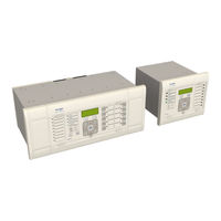
GE MiCOM P40 Agile Technical Manual (458 pages)
Busbar Protection IED
Brand:
GE
| Category:
Protection Device
| Size: 34.13 MB
Table of Contents
Table of Contents
3
Chapter 1 Introduction
21
Trip Circuit Supervision Scheme
22
Rear Serial Port
22
Chapter Overview
23
Measurement Table
23
Trip Circuit Supervision Scheme
23
Cip
23
Foreword
24
Target Audience
24
Typographical Conventions
24
Nomenclature
24
Cip
24
Product Scope
25
Cip
25
Features and Functions
26
Protection Functions
26
Control Functions
26
Measurement Functions
26
Cip
26
Communication Functions
27
Cip
27
Compliance
28
Functional Overview
29
Cip
29
Figure 1: Functional Overview
29
Ordering Options
30
Chapter 2 Safety Information
31
Chapter Overview
33
Chapter Overview Health and Safety Symbols
33
Installation, Commissioning and Servicing
36
Lifting Hazards
36
Electrical Hazards
36
UL/CSA/CUL Requirements
37
Fusing Requirements
37
Equipment Connections
38
Protection Class 1 Equipment Requirements
38
Pre-Energization Checklist
39
Peripheral Circuitry
40
Upgrading/Servicing
40
Decommissioning and Disposal
41
Chapter 3 Hardware Design
43
Chapter Overview
45
Hardware Architecture
46
Figure 2: Hardware Architecture
46
Mechanical Implementation
47
Housing Variants
47
Figure 3: Exploded View of IED
47
List of Boards
48
Front Panel
49
Figure 4: Front Panel (80TE)
49
Top Compartment with Hinged Cover
50
Keypad
50
Liquid Crystal Display
50
Front Serial Port (SK1)
50
Front Parallel Port (SK2)
51
Fixed Function Leds
51
Function Keys
52
Programable Leds
52
Rear Panel
53
Figure 5: Rear View of Populated 80TE Case
53
Figure 6: Terminal Block Types
54
GE MiCOM P40 Agile Technical Manual (108 pages)
Redundant Ethernet Boards
Brand:
GE
| Category:
Medical Equipment
| Size: 1.49 MB
Table of Contents
Table of Contents
3
Chapter 1 Introduction
7
Chapter Overview
9
Foreword
10
Target Audience
10
Typographical Conventions
10
Nomenclature
11
Product Scope
11
Features and Functions
12
Compliance
14
Chapter 2 Safety Information
15
Chapter Overview
17
Health and Safety
18
Symbols
19
Installation, Commissioning and Servicing
20
Lifting Hazards
20
Electrical Hazards
20
UL/CSA/CUL Requirements
21
Fusing Requirements
21
Equipment Connections
22
Protection Class 1 Equipment Requirements
22
Pre-Energisation Checklist
23
Peripheral Circuitry
23
Upgrading/Servicing
25
Decommissioning and Disposal
26
Regulatory Compliance
27
EMC Compliance: 2014/30/EU
27
LVD Compliance: 2014/35/EU
27
R&TTE Compliance: 2014/53/EU
27
UL/CUL Compliance
27
Chapter 3 Hardware Design
29
Chapter Overview
31
Board Versions
32
Board Connections
33
Chapter 4 Configuration
35
Chapter Overview
37
Configuring IP Addresses
38
Configuring the IED IP Address
38
Configuring the REB IP Address
38
Configuring the Last Octet (SHP, DHP, RSTP)
40
Redundant Ethernet Configurator
43
Connecting the IED to a PC
43
Installing the Configurator
43
Starting the Configurator
44
Device Identification
44
Selecting the Device Mode
44
Filter by Board Type
44
Password Confguration
44
IP Address Configuration
44
SNTP IP Address Configuration
45
Check MAC Table for Connected Equipment
45
PRP Configuration
45
HSR Configuration
45
RSTP Configuration
46
Bridge Parameters
46
Port Parameters
46
Port States
47
Failover Configuration
47
Filtering Database
47
End of Session
48
PRP/HSR Configurator
49
Connecting the IED to a PC
49
Installing the Configurator
49
Starting the Configurator
49
PRP/HSR Device Identification
50
Selecting the Device Mode
50
PRP/HSR IP Address Configuration
50
SNTP IP Address Configuration
50
Check for Connected Equipment
50
PRP Configuration
51
HSR Configuration
51
End of Session
51
RSTP Configurator
52
Connecting the IED to a PC
52
Installing the Configurator
52
Starting the Configurator
52
RSTP Device Identification
53
RSTP IP Address Configuration
53
SNTP IP Address Configuration
53
Check for Connected Equipment
53
RSTP Configuration
54
Bridge Parameters
54
Port Parameters
54
Port States
54
End of Session
55
Switch Manager
56
Installation
56
Setup
57
Network Setup
57
Bandwidth Used
57
Reset Counters
57
Check for Connected Equipment
58
Mirroring Function
58
Ports On/Off
58
Vlan
58
End of Session
59
Related Products
GE MiCOM P543i
GE MiCOM P545i
GE MiCOM P141 Agile
GE MiCOM P142 Agile
GE MiCOM P143 Agile
GE MiCOM P144 Agile
GE MiCOM P145 Agile
GE P485
GE P442
GE P444
GE Categories
Refrigerator
Ranges
Microwave Oven
Air Conditioner
Dishwasher
More GE Manuals