beautypg.com
Manuals
Brands
GE Manuals
Relays
MOTOR MANAGEMENT RELAY 469
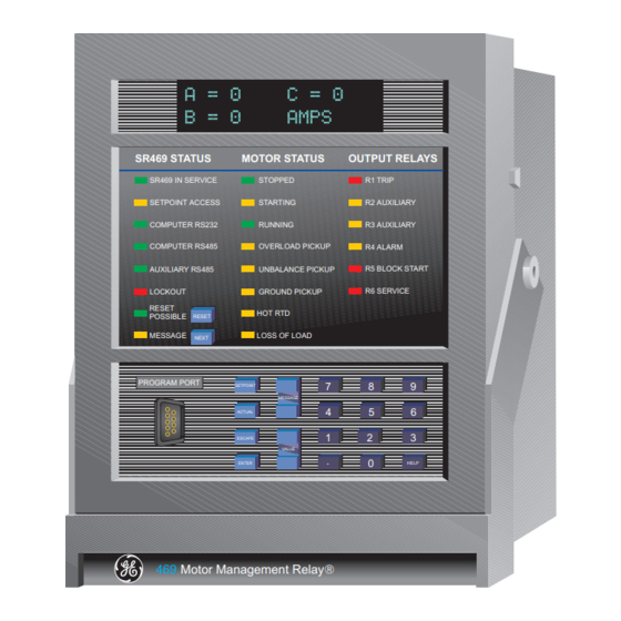
GE MOTOR MANAGEMENT RELAY 469 Manuals
Manuals and User Guides for GE MOTOR MANAGEMENT RELAY 469. We have
1
GE MOTOR MANAGEMENT RELAY 469 manual available for free PDF download: Instruction Manual
GE MOTOR MANAGEMENT RELAY 469 Instruction Manual (311 pages)
Brand:
GE
| Category:
Relays
| Size: 5.57 MB
Table of Contents
Table of Contents
5
1 Introduction
13
Overview
13
Description
13
Order Information
16
Other Accessories
16
Specifications
17
2 Installation
23
Mechanical
23
Description
23
Product Identification
24
Installation
24
Installation
25
Unit Withdrawal and Insertion
26
Terminal Locations
28
Electrical
30
Typical Wiring Diagram
30
Typical Wiring
31
Control Power
31
Phase Current Inputs
32
Ground Current Input
32
Differential Current Inputs
34
Voltage Inputs
35
Digital Inputs
35
Analog Inputs
36
Analog Outputs
36
Rtd Sensor Connections
37
Description
37
Reduced Rtd Lead Number Application
38
Two Wire Rtd Lead Compensation
39
GROUNDING of Rtds
39
Output Relays
40
Drawout Indicator
41
Rs485 Communications Ports
42
Typical 2 Speed Motor Wiring
43
Dielectric Strength Testing
44
3 Operation
45
Overview
45
Faceplate
45
Display
46
Led Indicators
46
A 469 STATUS LED INDICATORS
46
Motor Status Led Indicators
47
Output Relay Led Indicators
47
Rs232 Program Port
47
Keypad
48
Entering Alphanumeric Text
48
Entering +/- Signs
48
Setpoint Entry
49
Procedure
49
4 Setpoint
49
Overview
51
Trips/Alarms/Blocks Defined
51
Trips
51
Alarms
51
Relay Assignment Practices
52
Setpoint Message Map
53
S1 469 Setup
54
Passcode
54
Function
54
Enabling Passcode Protection
54
Preferences
55
Serial Ports
56
Real Time Clock
56
Default Messages
57
Adding Default Messages
57
Removing Default Messages
57
Message Scratchpad
58
Clear Data
59
Installation
60
S2 System Setup
61
Current Sensing
61
Function
61
Examples
62
Voltage Sensing
62
Power System
63
Serial Communication Control
63
Reduced Voltage
64
S3 Digital Inputs
66
Description
66
Access Switch
66
Test Switch
66
Emergency Restart
66
Remote Reset
66
Starter Status
67
Assignable Digital Inputs
67
Digital Input Function: Remote Alarm
68
Digital Input Function: Remote Trip
68
Digital Input Function: Speed Switch Trip
69
Digital Input Function: Load Shed Trip
69
Digital Input Function: Pressure Switch Alarm
69
Digital Input Function: Pressure Switch Trip
70
Digital Input Function: Vibration Switch Alarm
70
Digital Input Function: Vibration Switch Trip
70
Digital Input Function: Digital Counter
71
Function
71
Example
71
Function
72
Example
72
Digital Input Function: Tachometer
72
Digital Input Function: General Switch A-D
73
Digital Input Function: Capture Trace
73
Digital Input Function: Simulate Pre-Fault
73
Digital Input Function: Simulate Fault
73
S4 Output Relays
74
Description
74
Relay Reset Mode
74
Example
74
Force Output Relay
75
S5 Thermal Model
76
Motor Thermal Limits
76
Thermal Model
78
Overload Curve Setup
79
Function
81
Custom Overload Curve
87
Unbalance Bias
92
Motor Cooling
93
Hot/Cold Curve Ratio
94
Rtd Bias
94
S6 Current Elements
96
Short Circuit
96
Overload Alarm
97
Mechanical Jam
97
Undercurrent
98
Function
98
Example
98
Current Unbalance
99
Function
99
Example
99
Ground Fault
100
Phase Differential
102
S7 Motor Starting
103
Acceleration Timer
103
Start Inhibit
104
Function
104
Example
104
Jogging Block
105
Function
105
Starts / Hour
105
Time between Starts
105
Restart Block
106
S8 Rtd Temperature
107
Rtd Types
107
Rtds 1 to 6
108
Rtds 7 to 10
109
Rtd 11
110
Rtd 12
111
Open Rtd Sensor
112
Rtd Short/Low Temp
112
S9 Voltage Elements
113
Undervoltage
113
Overvoltage
114
Phase Reversal
114
Frequency
115
S10 Power Elements
116
Power Measurement Conventions
116
Power Factor
117
Reactive Power
118
Underpower
119
Function
119
Example
119
Reverse Power
120
Torque Setup
121
Overtorque Setup
121
S11 Monitoring
122
Trip Counter
122
Starter Failure
122
Current, Kw, Kvar, Kva Demand
124
Pulse Output
126
S12 Analog I/O
127
Analog Outputs 1 to 4
127
Analog Output Table
128
Analog Inputs 1-4
129
Function
130
Analog in Diff 1-2
131
Analog in Diff 3-4
132
S13 469 Testing
133
Simulation Mode
133
Pre-Fault Setup
134
Fault Setup
135
Test Output Relays
136
Test Analog Output
136
Comm Port Monitor
137
Multilin Use Only
137
S14 Two-Speed Motor
138
Description
138
Speed2 O/L Setup
138
Speed2 Undercurrent
140
Speed2 Acceleration
141
5 Actual Values
143
Overview
143
Actual Values Messages
143
A1 Status
144
Motor Status
144
Last Trip Data
145
Alarm Status
147
Start Blocks
149
Digital Inputs
150
Real Time Clock
150
A2 Metering Data
151
Current Metering
151
Temperature
152
Voltage Metering
153
Speed
153
Power Metering
154
Torque Alarm Message
154
Demand Metering
155
Analog Inputs
156
Phasors
157
A3 Learned Data
159
Motor Starting
159
Average Motor Load
159
Rtd Maximums
160
Analog in Min/Max
161
A4 Maintenance
162
Trip Counters
162
General Counters
164
Timers
164
A5 Event Recorder
165
Event01 to Event40
165
A6 Product Info
168
Model Info
168
Calibration Info
168
Diagnostics
169
Diagnostic Messages for Operators
169
Example
169
Flash Messages
170
6 Communications
173
Modbus Communications
173
Electrical Interface
173
Modbus Rtu Protocol
173
Data Frame Format and Data Rate
173
Data Packet Format
174
Algorithm
175
Timing
175
Supported Modbus Functions
176
Overview
176
Function Codes 01/02: Read Relay Coil / Digital Input Status
176
C MESSAGE FORMAT and EXAMPLE, FUNCTION 01
177
D MESSAGE FORMAT and EXAMPLE, FUNCTION 02
178
Function Codes 03/04: Read Setpoints/Actual Values
180
Function Code 05: Execute Operation
181
Function Code 06: Store Single Setpoint
182
Function Code 07: Read Device Status
183
Function Code 08: Loopback Test
184
Function Code 16: Store Multiple Setpoints
185
Function Code 16: Performing Commands
186
Error Responses
187
Description
187
Memory Map
188
Memory Map Information
188
User Definable Memory Map Area
188
Event Recorder
189
Waveform Capture
189
Memory Map
189
Memory Map Format Codes
233
7 Testing
241
Overview
241
Test Setup
241
Phase Current Accuracy Test
242
Ground (1A/5A) and Differential Accuracy Test
243
Ge Power Management 50:0.025 Ground Accuracy Test
244
Digital Inputs and Trip Coil Supervision
246
Output Relays
248
Overload Curve Test
249
Power Measurement Test
250
Unbalance Test
251
Voltage Phase Reversal Test
252
Short Circuit Test
253
Description
255
Checking if Installation/Upgrade Is Required
256
Installing/Upgrading 469Pc
257
Startup & Communications Configuration
258
Saving Setpoints to a File
259
Firmware Upgrades
260
Loading Setpoints from a File
261
Entering Setpoints
262
Upgrading Setpoint Files to New Revision
263
Printing Setpoints & Actual Values
264
Trending
265
Waveform Capture
267
Phasors
269
Event Recording
270
Troubleshooting
271
A.1.1 Commissioning Summary
273
B.1.1 Description
287
C.1.1 Description
289
D.1.1 Ground Fault Cts for 50:0.025 a
291
D.1.2 Ground Fault Cts for 5 a Secondary Ct
292
D.1.3 Phase Cts
293
E.1.1 List of Figures
295
E.1.2 List of Tables
297
G.1.1 Warranty
301
Related Products
GE RPM11A
GE RPM11B
GE RPM11D
GE RPM11E
GE RPM11H
GE RPM11J
GE RPM14A
GE RPM14B
GE RPM14D
GE RPM 13A
GE Categories
Refrigerator
Ranges
Microwave Oven
Air Conditioner
Dishwasher
More GE Manuals