GE Multilin F35 Manuals
Manuals and User Guides for GE Multilin F35. We have 1 GE Multilin F35 manual available for free PDF download: Instruction Manual
GE Multilin F35 Instruction Manual (486 pages)
Multiple Feeder Protection System UR Series
Brand: GE Multilin
|
Category: Protection Device
|
Size: 9.45 MB
Table of Contents
-
-
-
Monitoring39
-
Inputs40
-
Power Supply41
-
Type Tests45
-
3.2 Wiring
55 -
-
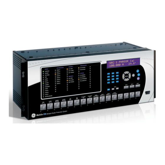
Faceplate105
-
Led Indicators106
-
Display114
-
Keypad114
-
Breaker Control115
-
Menus116
-
-
Settings
123 -
Overview
123 -
Product Setup
130-
Security130
-
Communications136
-
Modbus User Map154
-
Real Time Clock155
-
Fault Reports156
-
Oscillography158
-
Data Logger160
-
Demand162
-
Teleprotection184
-
Installation184
-
-
-
System Setup
186-
Ac Inputs186
-
Power System187
-
Signal Sources188
-
Breakers191
-
Flexcurves198
-
-
Flexlogic
205-
Flexlogic™ Rules213
-
-
Flexlogic Timers218
-
Flexelements220
-
-
Grouped Elements
225-
Overview225
-
Setting Group225
-
Phase Current225
-
-
Neutral Current225
-
Neutral Current233
-
Ground Current235
-
Voltage Elements237
-
-
-
Control Elements
243-
Overview243
-
Selector Switch244
-
Underfrequency250
-
Autoreclose251
-
Digital Elements257
-
Digital Counters260
-
8-Bit Switches262
-
Trip Bus269
-
-
-
Inputs/Outputs
272-
Contact Inputs272
-
Virtual Inputs274
-
Contact Outputs275
-
Virtual Outputs277
-
Remote Devices278
-
Remote Inputs279
-
Resetting281
-
-
-
Dcma Outputs291
-
-
Testing
294-
Test Mode294
-
-
Actual Values
297 -
Overview
297 -
Status
299-
Contact Inputs299
-
Virtual Inputs299
-
Remote Inputs299
-
Contact Outputs300
-
Virtual Outputs301
-
Autoreclose301
-
Remote Devices301
-
Digital Counters302
-
Flex States302
-
Ethernet303
-
Direct Inputs303
-
Ethernet Switch305
-
-
6.3 Metering
306-
Sources309
-
Flexelements315
-
Records
317-
Fault Reports317
-
Event Records317
-
Oscillography318
-
Data Logger318
-
-
-
Commands and
321 -
Commands
321-
Commands Menu321
-
Virtual Inputs321
-
Clear Records321
-
Targets Menu323
-
Target Messages323
-
Relay Self-Tests323
-
-
7.2 Targets
323 -
Fault Locator
329 -
Commissioning
333 -
Testing
333 -
Flexanalog
335 -
Parameter List
335-
Flexanalog List335
-
-
B. Modbus
351-
Communications
351 -
Introduction351
-
Physical Layer351
-
Data Link Layer351
-
Algorithm352
-
-
File Transfers
356 -
Memory Mapping
358-
Data Formats405
-
-
Iec 61850
423-
Communications
423 -
Introduction423
-
-
Overview
423 -
-
Overview429
-
Fixed Goose429
-
C.4.1 Overview429
-
Overview433
-
C.5.1 Overview433
-
About ICD Files435
-
About Scd Files439
-
-
Acsi Conformance
444 -
Logical Nodes
448 -
Dnp Point Lists
468-
Counters470
-
E.2.3 Counters470
-
Analog Inputs471
-
Change Notes
473 -
Abbreviations
476 -
Warranty
478