beautypg.com
Manuals
Brands
GE Manuals
Relays
P50 Agile P253
GE P50 Agile P253 Manuals
Manuals and User Guides for GE P50 Agile P253. We have
1
GE P50 Agile P253 manual available for free PDF download: Technical Manual
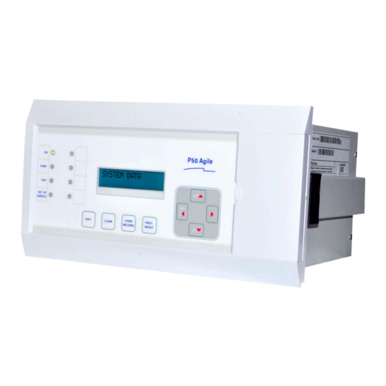
GE P50 Agile P253 Technical Manual (298 pages)
Motor Protection Relay
Brand:
GE
| Category:
Relays
| Size: 3.35 MB
Table of Contents
2.3.8 Configuration Menu
66
Table of Contents
66
View / Edit Settings
68
Configuration
68
No Operation
74
Group 1
74
Group 1
76
Disabled
76
System Config
76
Enabled
76
Editable Setting
76
Editable Setting
77
Group 1
77
Disabled
77
Enabled / Disabled
78
6 Protection Functions 1 Chapter Overview
157
Motor Starting and Running (Stall Protection) (48/51LR/50S/14)
158
Stall Protection Description
158
Prolonged Start
158
Locked Rotor During Starting - (Stall Time < Start Time)
159
Stall During Running
159
Starts Inhibition
160
Time between Starts
162
Number of Starts Limitation
160
Thermal Overload Function
163
Thermal Replica
164
Thermal Trip
164
Thermal Overload Protection Implementation
166
Thermal Lockout
167
Inhibit Thermal Trip During Motor Start-Up (Inh Trip Dur St)
167
Emergency Restart
168
Overcurrent Protection Principles
168
IDMT Characteristics
168
Principle of Protection Function Implementation
169
Timer Hold Facility/Reset Characteristics
170
Phase Overcurrent Protection (Motor Short Circuit Protection)
171
Phase Overcurrent Protection Implementation
171
Negative Sequence Overcurrent Protection
172
Loss of Phase While Starting and Running
172
Negative Sequence Overcurrent Protection Implementation
172
Negative Sequence Overcurrent Protection Logic
173
Earth Fault Protection
173
Earth Fault Protection Elements
173
Earth Fault Protection Logic
174
Sensitive Earth Fault Protection
174
Sensitive Earth Fault Protection (Ordering Option)
175
Restricted Earth Fault Protection
175
Restricted Earth Fault Implementation
176
Application Note
176
High Impedance REF
176
Loss of Load Protection Function
177
Circuit Breaker Fail Protection
178
Circuit Breaker Fail Implementation
178
Circuit Breaker Fail Logic
179
Inrush Current Blocking Function (2ND Harm Blocking)
180
Second Harmonic Blocking Implementation
180
8 Monitoring & Control 1 Chapter Overview
205
Monitoring Functions (Event, Fault, Disturbance, Start-Up Current Record)
206
Event Record
206
Alarm Record
207
Fault Record
207
Maintenance Record
207
Disturbance Record
207
Start-Up Current Record
208
Record Control
208
Display of Measuring Parameters
208
MEASUREMENT 1 Submenu
208
MEASUREMENT 2 Submenu
209
Opto Inputs
209
Output Relays
210
Output Relay Function Assignment
210
O/P Relay Configuration
213
O/P Contact Open Time
213
Programmable Leds
214
Logic Equations
215
CB Monitoring
216
CB Open Supervision
216
CB Open Operation Alarm
217
CB Control
217
Local Control Using IED Menu
218
Remote Control
218
Trip Circuit Supervision
219
Calculations for External Resistor
220
Self-Diagnostic Features
220
Watchdog Feature
220
9 Scada Communications 1 Chapter Overview
225
Modbus
226
Physical Connection and Link Layer Overview
226
MODBUS Functions
226
Protocol Mapping
226
Overview
231
Physical Connection and Link Layer
232
Cyclic Measurements
232
General Interrogation (GI)
232
Initialisation
232
Time Synchronisation
232
Spontaneous Events
232
Commands
233
Test Mode
233
Configuration
233
Protocol Mapping
234
Disturbance Records
233
10 Installation 1 Chapter Overview
251
2.1.2 Unpacking the Goods
252
Handling the Goods
252
Installation
252
Receipt of the Goods
252
Unpacking the Goods
252
Storing the Goods
252
Dismantling the Goods
252
Flush Panel Mounting
253
Mounting the Device
253
Relay Connection
254
Cables and Connectors
255
Terminal Blocks
256
Ct/Auxiliary Power/Input/ Output Connections
256
Current Transformer (CT) Circuit
255
Relay Operating Condition
255
Power Supply Connections
256
Rear Serial Port Connection
256
Current Transformers
257
Earth Connection
257
Case Dimensions
258
EIA(RS) 485 Connections
258
Output Relay Connections
258
USB Connection
258
2.1.3 Storing the Goods
252
2.1.4 Dismantling the Goods
253
2.3.3 Terminal Blocks
256
2.3.2 Cables and Connectors
256
11 Commissioning Instructions 1 Chapter Overview
261
2.1.4 Test Leds
262
Commissioning
262
Commissioning Test Menu
262
Test Mode
262
Test Pattern
262
Contact Test
262
Test Leds
262
Opto Input Status Check
262
Opto Output Status Check
263
Commissioning Test Equipment Required
263
Battery Check
263
External Circuitry Check
263
Check Relay Settings
264
Protection Timing Checks
264
Overcurrent Check
264
Connecting the Test Circuit
264
CT Polarity
264
Checking the Operating Time
265
Performing the Test
265
Thermal Overload Protection
265
Connect the Test Circuit
266
Perform the Test
266
Verify the Operating Time
266
Final Check
268
Onload Checks
268
2.1.3 Contact Test
262
2.1.2 Test Pattern
262
2.1.7 Commissioning Test Equipment Required
263
2.1.8 Battery Check
263
2.1.6 Opto Output Status Check
263
2.1.5 Opto Input Status Check
263
2.1.11 Protection Timing Checks
264
2.1.10 Check Relay Settings
264
2.1.9 External Circuitry Check
264
2.1.12 Thermal Overload Protection
266
2.1.13 Onload Checks
268
Related Products
GE P24DM
GE P24NM
GE P642
GE P742
GE MiCOM P40 Agile P14D
GE MiCOM P40 Agile P94V
GE P54B
GE P54E
GE PJV Series
GE Agile P50 Series
GE Categories
Refrigerator
Ranges
Microwave Oven
Air Conditioner
Dishwasher
More GE Manuals