beautypg.com
Manuals
Brands
gefran Manuals
Controller
GFX4
gefran GFX4 Manuals
Manuals and User Guides for gefran GFX4. We have
2
gefran GFX4 manuals available for free PDF download: Configuration And Programming Manual, Installation And Operation Manual
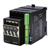
gefran GFX4 Configuration And Programming Manual (78 pages)
4-ZONE MODULAR POWER CONTROLLER
Brand:
gefran
| Category:
Controller
| Size: 1.35 MB
Table of Contents
Table of Contents
3
Introduction
4
Field of Use
4
Characteristics of Personnel
4
Structure of this Manual
5
Instrument Architecture
6
Serial Communication (Modbus)
7
Connection
8
Inputs
10
Main Input
10
CT AUXILIARY INPUT (Ammeter)
15
VOLTAGE VALUE on the LOAD (Voltmeter)
17
Auxiliary Analog Input (Lin/Tc)
19
Digital Inputs
21
Using a Function Associated with Digital
22
Input and Via Serial
22
Using a Function of Digital Input 1 to Enable
23
At Software on
23
Alarms
24
GENERIC ALARMS AL1, AL2, AL3 and AL4
24
LBA ALARM (Loop Break Alarm)
29
HB ALARM (Heater Break Alarm)
30
Alarm Sbr - Err
32
(Probe in Short or Connection Error)
32
Power Fault ALARMS
33
No_Current
33
Overheat Alarm
35
Outputs
36
Settings
40
Setting the Setpoint
40
Setpoint Control
41
Controls
43
Pid Heat/Cool Control
43
Automatic / Manual Control
47
Hold Function
47
Manual Power Correction
47
Manual Tuning
48
Autotuning
48
Selftuning
50
Softstart
51
Start Mode
51
Software Shutdown
52
Hot Runners Control
53
Fault Action Power
53
Power Alarm
53
Softstart for Preheating
55
HEATING OUTPUT (Fast Cycle)
56
Power Control
56
Ssr Control Modes
56
Virtual Instrument Control
59
Hw/Sw Information
60
Instrument Configuration Sheet
63
Programmable Parameters
63
gefran GFX4 Installation And Operation Manual (36 pages)
4 ZONE MODULAR POWER CONTROLLER
Brand:
gefran
| Category:
Controller
| Size: 1.83 MB
Table of Contents
Index
1
Graphic Symbols
1
Preliminary Instructions
2
General Description
2
Electrical Power Supply
3
Notes on Electrical Safety and Electromagnetic Compatibility
3
Instrument Power Supply
3
Installation and Connection 3
3
EMC Emission
4
EMC Immunity
4
LVD Safety
4
Insulation Diagram
5
Dimensions
6
Model Without Fuse Holder
6
Model with Fuse Holder
6
Installation
7
Power Connections
8
Cleaning/Checking or Replacing the Fan
9
Inserting the Field Bus Interface Board
9
Electrical Connections
10
Input/Output Connections
11
Description of Leds
11
Description of Rotary Switches
11
Connector J1 Outputs
12
Connector J1
12
Connection Scheme for Logic/Continuous Outputs
12
Connection for Logic/Continuous Outputs
13
Connection Scheme for Triac Outputs
14
Connection Scheme for Relay Outputs
14
Connector J2 Power Supply/Digital Inputs
15
Connector J3 Auxiliary Inputs
16
Connector J4 Inputs
17
Description of Dip-Switches
18
Serial Communication Ports
19
Port2: Fieldbus Modbus Rtu/Modbus RTU Interface
20
Port2: Fieldbus Modbus Rtu/Profibus DP Interface
21
Port2: Fieldbus Modbus Rtu/Canopen Interface
22
Port2: Fieldbus Modbus Rtu/Devicenet Interface
23
Port2: Modbus RTU / Ethernet Modbus TCP Interface
24
Connection Example: Communication Ports
25
Integration of GFX4 with GEFLEX Modules Connected in RS485 Modbus
25
Power Section
26
Connection Example for 4 Single-Phase Loads
26
Connection Example for One 3-Phase Load, Open Triangle
27
Connection Example for Two 3-Phase Loads, Star Without Neutral
27
Connection Example for Two 3-Phase Loads, Closed Triangle
28
Installation of “Modbus” Serial Network
29
“AUTOBAUD SERIAL 1” Sequence
30
“AUTONODE PORT 1” Sequence
30
Technical Data
31
Technical / Commercial Information
34
Accessories
34
Related Products
gefran GFX4-IR
gefran GEFLEX GFX-M1 Series
gefran GEFLEX GFX-S1 Series
gefran GEFLEX GFX-E1 Series
gefran GFXTERMO4
gefran GFX4-IR 30
gefran GFX4-IR 60
gefran GFX4-IR 80
gefran GFW ADV
gefran GFW 500A
gefran Categories
Controller
Control Unit
Relays
Inverter
DC Drives
More gefran Manuals