beautypg.com
Manuals
Brands
Honeywell Manuals
Control Panel
Fire-Lite Alarms MS-9050UDE
Honeywell Fire-Lite Alarms MS-9050UDE Manuals
Manuals and User Guides for Honeywell Fire-Lite Alarms MS-9050UDE. We have
1
Honeywell Fire-Lite Alarms MS-9050UDE manual available for free PDF download: Wiring Manual
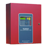
Honeywell Fire-Lite Alarms MS-9050UDE Wiring Manual (80 pages)
Intelligent Control Panel, SLC
Brand:
Honeywell
| Category:
Control Panel
| Size: 3.06 MB
Table of Contents
Table of Contents
5
Section 1: Introduction
8
Scope
8
1: Reference Documentation
8
Overview
10
Polling Protocols
10
1: Available Protocols
10
2: Protocol Use
10
Devices
10
1: Isolator Modules
10
2: Monitor Modules
10
3: Control Modules
11
4: Relay Modules
11
5: Multiple Input/Output Modules
11
6: Intelligent Detectors
11
Manual Pull Station
12
8: Wireless Gateway
12
9: 300 Series Addressable Devices
12
10: 900 Series Addressable Devices
12
SLC Capacity
12
SLC Performance
12
Surge Suppression
13
LED Operation
13
Section 2: Wiring Requirements
14
Wire Sizing
14
1: CLIP (Classic Loop Interface Protocol) Mode
14
2: Litespeed Mode
14
Measuring Resistance & Length
14
1: Two-Wire SLC - Class B
14
2: Four-Wire SLC Class a and Class X
15
Shield Wire Termination
16
Control Panel Terminal Blocks
17
1: Ms-9200
17
2: Ms-9600, Ms-9600Ls, & Ms-9600Udls
17
3: MS-9200UDLS (Software Version 3.0)
18
4: MS-9200UD & MS-9200UDLS (Versions 1 and 2)
18
5: Ms-9050Ud
18
6: Es-50X
19
7: Es-200X
19
Section 3: SLC Circuits Without Isolators
20
Overview
20
NFPA Class B SLC
20
NFPA Class a SLC
21
Section 4: SLC Circuits with Isolators
22
Fault Isolator Devices
22
1: Isolating an SLC Branch
22
2: Wiring an Isolator Module
22
NFPA Class B SLC Using Isolator Modules
24
NFPA Class a SLC Using Isolator Modules
26
NFPA Class X SLC Using Isolator Modules
27
Section 5: Monitor Modules
28
Descriptions
28
1: Addressable Monitor Modules
28
2: Zone Interface Modules
30
3: Dual Monitor Module
32
4: Mini Monitor Module
32
Installation
32
1: Setting an SLC Address for a Single Point Module
33
2: Setting an SLC Address for a Multi-Point Module
33
MMF-300 Wiring Diagrams
34
1: Wiring a NFPA Class B IDC with an MMF-300
34
2: Wiring a NFPA Class a IDC with an MMF-300
35
3: MMF-300 Wiring for Emergency Alarm System Applications
36
MMF-300-10 Wiring Diagrams
37
1: Wiring a NFPA Class B IDC with an MMF-300-10
37
2: Wiring a NFPA Class a IDC with an MMF-300-10
38
MDF-300 Wiring Diagrams
39
1: Wiring a NFPA Class B IDC with an MDF-300
39
MMF-302 Wiring Diagrams
40
1: Wiring a NFPA Class B IDC with an MMF-302
40
2: Wiring a NFPA Class a IDC with an MMF-302
41
MMF-302-6 Wiring Diagrams
42
1: Wiring a NFPA Class B IDC with an MMF-302-6
42
2: Wiring a NFPA Class a IDC with an MMF-302-6
43
Section 6: Control Modules
44
Description
44
CMF-300 Installation
44
1: Setting an SLC Address for a CMF-300 Module
44
2: Wiring a Notification Appliance Circuit (NAC) with a CMF-300
44
Wiring a CMF-300 Module
44
1: Wiring a Class B NAC (Two-Wire) with Addressable Control Modules
44
2: Wiring a Class a NAC (Four-Wire) with Addressable Control Modules
45
CMF-300-6 Installation
46
1: Cabinet Installation
46
2: Setting an SLC Address for an CMF-300-6 Module
46
3: Setting Nacs as Class B or Class a
46
4: Disabling Unused Module Addresses
46
5: Short Circuit Protection
46
6: Features Not Supported
46
7: Circuit Board Information
47
Wiring a CMF-300-6 Module
48
1: Wiring a Class B NAC (Two-Wire)
48
2: Wiring a Class a NAC (Four-Wire)
49
Section 7: Relay Modules
50
Description
50
CRF-300 Installation & Wiring
50
1: Setting an SLC Address for a CRF-300 Module
50
2: Wiring a CRF-300 Module (Form-C Relay)
50
CRF-300-6 Circuit Board Information
51
CRF-300-6 Installation & Wiring
52
1: Cabinet Installation
52
2: Setting an SLC Address for a CRF-300-6 Module
52
3: Disabling Unused Module Addresses
52
4: Wiring a CRF-300-6 Module (Form-C Relay)
52
Section 8: Multiple Input/Output Modules
53
Description
53
CDRM-300 Installation & Wiring
53
1: Setting an SLC Address for a CDRM-300 Module
53
2: Wiring a CDRM-300 Module (Form-C Relay)
53
Section 9: Intelligent Detector Bases and Wireless Gateway
54
Description
54
Setting the Detector Address
54
Wiring a Detector Base
55
Wiring an Isolator Base
56
Wiring a Relay Base
56
Wiring a Sounder Base
57
Wiring the W-GATE
57
1: SLC Connections
58
2: W-GATE Powered by the SLC
58
3: W-GATE Powered by a Regulated, External +24VDC Power Source
59
Section 10: Addressable Beam Detectors
60
Description
60
Installation and Wiring
60
1: Setting an SLC Address for a Beam Detector
60
2: Wiring a Beam Detector
60
Section 11: Addressable Manual Pull Station
62
Description
62
Installation
62
1: Setting an SLC Address
62
2: Wiring a Manual Pull Station
62
Appendix A: Power Considerations
63
A.1: Supplying Power to 24 VDC Detectors and Nacs
63
A.1.1: Resistance and Size
63
A.2: Supervising 24 VDC Power
64
Appendix B: Surge Suppression
65
B.1: Introduction
65
B.2: Installation
65
B.2.1: Wiring Diagram for MS-9200
66
B.2.2: Wiring Diagram for MS-9600, MS-9600LS, MS-9600UDLS, MS-9200UD, MS-9200UDLS, and MS-9050UD
67
B.2.3: Wiring Diagram for ES-50X and ES-200X
68
Appendix C: Terminal Conversion Charts for New & Legacy Devices
69
C.1: Crf-300
69
C.2: CMF-300 and MMF-302
69
C.3: Mmf-300
70
C.4: Mdf-300
71
Appendix D: Intelligent Detector Base Layouts for Legacy Devices
72
D.1: B350LP or B501 Detector Base
72
D.2: B224BI Isolator Base
73
D.3: B224RB Relay Base
73
D.4: B501BH(-2) and B501BHT(-2) Sounder Bases
74
Appendix E: Canadian Versions of SLC Devices
75
Index
77
Related Products
Honeywell Fire-Lite Alarms MS-9050UD
Honeywell Fire-Lite Alarms MS-9050UDC
Honeywell Fire-Lite Alarms MS-9200
Honeywell Fire-Lite Alarms MS-9200E
Honeywell Fire-Lite Alarms MS-9600E
Honeywell Fire-Lite Alarms MS-9600LS
Honeywell Fire-Lite Alarms MS-9600LSC
Honeywell Fire-Lite Alarms MS-9600LSE
Honeywell Fire-Lite Alarms MS-9600UDLS
Honeywell Fire-Lite Alarms MS-9200UDE
Honeywell Categories
Thermostat
Controller
Control Unit
Security Camera
Accessories
More Honeywell Manuals