beautypg.com
Manuals
Brands
IEI Technology Manuals
Desktop
ECW-281B-BTi
IEI Technology ECW-281B-BTi Manuals
Manuals and User Guides for IEI Technology ECW-281B-BTi. We have
1
IEI Technology ECW-281B-BTi manual available for free PDF download: User Manual
IEI Technology ECW-281B-BTi User Manual (135 pages)
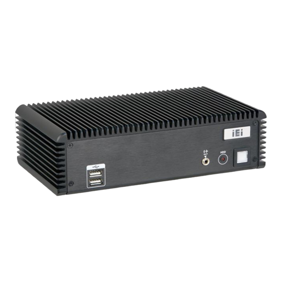
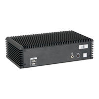
IEI Fanless Embedded System with Intel Celeron J1900 RoHS Compliant, Dual GbE LAN, COM Ports, USB 3.0
Brand:
IEI Technology
| Category:
Desktop
| Size: 4.23 MB
Table of Contents
Table of Contents
5
User Manual
1
Manual Conventions
4
1 Introduction
15
Overview
16
Benefits
16
Figure 1-1: ECW-281B-Bti Series Embedded System
16
Features
17
Model Variations
17
Table 1-1: Model Variations
17
External Overview
18
Front Panel
18
Figure 1-2: Front Panel
18
Rear Panel
19
Figure 1-3: Rear Panel
19
Bottom Surface
20
Figure 1-4: Bottom Surface
20
Internal Overview
21
Figure 1-5: Internal Overview
21
Technical Specifications
22
Table 1-2: Technical Specifications
23
Power Module Specifications (Optional)
24
Table 1-3: DC-To-DC Power Module Specifications
24
Dimensions
25
Figure 1-6: Dimensions (MM)
25
2 Unpacking
26
Unpacking
27
Packing List
27
Optional Items
28
Table 2-1: Package List
28
Table 2-2: Package List
28
3 Installation
29
Anti-Static Precautions
30
Installation Precautions
30
High Surface Temperature
31
Installation Procedure
32
Bottom Surface Removal
32
Configure the Jumper Settings
33
Clear CMOS
33
Figure 3-1: Bottom Surface Retention Screws
33
AT/ATX Mode Selection
34
Figure 3-2: Clear CMOS Button
34
Figure 3-3: AT/ATX Mode Select Switch Location
34
Hard Drive Installation
35
Figure 3-4:HDD Bracket Retention Screws
35
Table 3-1: AT/ATX Mode Select Switch Settings
35
Figure 3-5: HDD Retention Screws
36
Figure 3-6: HDD Installation
37
Full-Size Pcie Mini/Msata Card Installation
38
Figure 3-7: Pcie Mini Slot Location
38
Figure 3-8: Removing the Screw and Standoff for Half-Size Pcie Mini Card
38
Figure 3-9: Removing the Retention Screw
39
Figure 3-10: Inserting the Full-Size Pcie Mini Card into the Slot at an Angle
39
Half-Size Pcie Mini Card Installation
40
Figure 3-11: Securing the Full-Size Pcie Mini Card
40
Figure 3-12: Pcie Mini Slot Location
41
Figure 3-13: Removing the Screw
41
Figure 3-14: Inserting the Half-Size Pcie Mini Card into the Slot at an Angle
42
Figure 3-15: Securing the Half-Size Pcie Mini Card
42
Wireless LAN Module Installation (Optional)
43
Figure 3-16: Knockout Holes for Wireless Antenna
43
Figure 3-17: Pcie Mini Slot Location
43
Figure 3-18: Removing the Retention Screw
44
Figure 3-19: Inserting the WLAN Module
44
Figure 3-20: Securing WLAN Module and Connecting RF Cables
45
Figure 3-21: Securing SMA Connector and External Antenna Installation
45
Digital I/O Connection
46
Rs-422/485 Serial Port Connection
46
Serial Port Connector
46
Table 3-2: Digital I/O Connector Pinouts
46
Table 3-3: DB-9 RS-422/485 Pinouts
46
Mounting the System
47
Mounting with Mounting Brackets
47
Figure 3-22: Mounting Bracket Retention Screws
47
Table 3-4: RS-232 Serial Port Connector Pinouts
47
Mounting with VESA Mount Kit (Optional)
48
Figure 3-23: Wall-Mounting Bracket
48
Figure 3-24: Mount the Embedded System
49
Power -O N Procedure
50
Installation Checklist
50
Terminal Block Pinouts
50
Figure 3-25: Terminal Block Pinouts
50
Power-On Procedure
51
Driver Installation
51
Figure 3-26: Power Button
51
Ipmi Setup Procedure
52
4 Bios
53
Introduction
54
Starting Setup
54
Using Setup
54
Getting Help
55
Unable to Reboot after Configuration Changes
55
BIOS Menu Bar
55
Table 4-1: BIOS Navigation Keys
55
Main
56
BIOS Menu 1: Main
56
Advanced
57
System Date [XX/XX/XX]
57
System Time [XX:XX:XX]
57
ACPI Settings
58
BIOS Menu 2: Advanced
58
BIOS Menu 3: ACPI Settings
58
ACPI Sleep State [S3 (Suspend to RAM)]
58
Super IO Configuration
59
BIOS Menu 4: Super IO Configuration
59
Serial Port [Enabled]
59
Serial Port N Configuration
60
BIOS Menu 5: Serial Port N Configuration Menu
60
Change Settings [Auto]
60
Serial Port [Enabled]
60
Change Settings [Auto]
62
Serial Port [Enabled]
62
Hardware Monitor
65
BIOS Menu 6: Hardware Monitor
65
Smart Fan Function
66
BIOS Menu 7: Smart Fan Function Menu
66
CPU Smart Fan Control [Auto PWM Mode]
66
Temperature of off
66
Temperature of Start
66
Start PWM
67
Slope (Duty Cycle)
67
RTC Wake Settings
68
BIOS Menu 8: RTC Wake Settings
68
Wake System with Fixed Time [Disabled]
68
Serial Port Console Redirection
69
BIOS Menu 9: Serial Port Console Redirection
69
Console Redirection [Disabled]
69
Console Redirection Settings
70
BIOS Menu 10: Console Redirection Settings
70
Bits Per Second [115200]
70
Data Bits [8]
70
Stop Bits [1]
70
Iei Feature
72
BIOS Menu 11: Iei Feature
72
Auto Recovery Function [Disabled]
72
CPU Configuration
73
BIOS Menu 12: CPU Configuration
73
Intel Virtualization Technology [Enabled]
73
EIST [Enabled]
74
IDE Configuration
75
BIOS Menu 13: IDE Configuration
75
SATA Mode [AHCI Mode]
75
Serial-ATA Port 1/0 [Enabled]
75
USB Configuration
76
BIOS Menu 14: USB Configuration
76
SATA Port 1/0 Hotplug [Disabled]
76
USB Devices
76
Chipset
77
Legacy USB Support [Enabled]
77
North Bridge
78
BIOS Menu 15: Chipset
78
BIOS Menu 16: North Bridge
78
Intel IGD Configuration
79
BIOS Menu 17: Intel IGD Configuration
79
DVMT Pre-Allocated [256M]
79
DVMT Total Gfx Mem [Max]
79
South Bridge
80
BIOS Menu 18: South Bridge
80
Primary IGFX Boot Display [VBIOS Default]
80
PCI Express Configuration
81
BIOS Menu 19: PCI Express Configuration
81
Restore AC Power Loss [Last State]
81
Audio Controller [Enabled]
81
Security
82
BIOS Menu 20: Security
82
PCI Express Port N [Enabled]
82
Administrator Password
82
Boot
83
BIOS Menu 21: Boot
83
User Password
83
Bootup Numlock State [On]
83
Quiet Boot [Enabled]
83
Option ROM Messages [Keep Current]
84
UEFI Boot [Disabled]
84
Save & Exit
85
BIOS Menu 22: Save & Exit
85
Launch PXE Oprom [Disabled]
85
Save Changes and Reset
85
Discard Changes and Reset
85
Server Mgmt
86
BIOS Menu 23: Server Mgmt
86
Restore Defaults
86
Save as User Defaults
86
Restore User Defaults
86
System Event Log
87
BIOS Menu 24: System Event Log
87
SEL Components [Enabled]
87
Erase SEL [No]
87
BMC Network Configuration
88
BIOS Menu 25: System Event Log
88
When SEL Is Full [Do Nothing]
88
Configuration Address Source [Unspecified]
88
5 Troubleshooting and Maintenance
90
ECW-281B-Bti System Maintenance Overview
91
System Troubleshooting
91
The System Doesn't Turn on
91
The System Doesn't Boot up
92
More Troubleshooting
93
Component Replacement Procedure
93
SO-DIMM Replacement
94
Figure 5-1: SO-DIMM Location
94
Figure 5-2: SO-DIMM Installation
95
6 System Components
96
Embedded System Motherboard
97
WAFER-BT-I1 Motherboard Overview
97
Figure 6-1: WAFER-BT-I1 Jumper and Connector Locations
97
Peripheral Interface Connectors
98
Table 6-1: Peripheral Interface Connectors
98
Internal Peripheral Connectors
99
DC-IN Power Connector
99
Audio Connector
99
Figure 6-2: +12V DC-IN Power Connector Location
99
Table 6-2: +12V DC-IN Power Connector Pinouts
99
Battery Connector
100
Figure 6-3: Audio Connector Location
100
Figure 6-4: Battery Connector Location
100
Table 6-3: Audio Connector Pinouts
100
Buzzer Connector
101
DDR3L SO-DIMM Slot
101
Figure 6-5: Buzzer Connector Location
101
Table 6-4: Battery Connector Pinouts
101
Table 6-5: Buzzer Connector Pinouts
101
Digital I/O Connector
102
Figure 6-6: DDR3L SO-DIMM Slot Location
102
Figure 6-7: Digital I/O Connector Location
102
Table 6-6: Digital I/O Connector Pinouts
102
Front Panel Connector
103
Iris-1010 Module Slot
103
Figure 6-8: Front Panel Connector Location
103
Figure 6-9: Iris-1010 Module Slot Location
103
Table 6-7: Front Panel Connector Pinouts
103
Pcie Mini Card/Msata Slot
104
Power Button Connector
104
Figure 6-10: Pcie Mini Card Slot Location
104
Reset Button Connector
105
Figure 6-11: Power Button Connector Location
105
Figure 6-12: Reset Button Connector Location
105
Table 6-8: Power Button Connector Pinouts
105
Serial Port Connectors
106
Figure 6-13: RS-232 Serial Port Connectors Locations
106
Table 6-9: Reset Button Connector Pinouts
106
Table 6-10: RS-232 Serial Port Connector Pinouts
106
RS-422/485 Serial Port Connector
107
Figure 6-14: RS-422/485 Connector Location
107
Table 6-11: RS-422/485 Connector Pinouts
107
Table 6-12: DB-9 RS-422/485 Pinouts
107
SATA 3Gb/S Drive Connector
108
SATA Power Connector
108
Figure 6-15: SATA 3Gb/S Drive Connectors Locations
108
USB Connectors
109
Figure 6-16: SATA Power Connector Location
109
Figure 6-17: USB Connectors Locations
109
Table 6-13: SATA Power Connector Pinouts
109
Table 6-14: USB Connectors Pinouts
109
External Peripheral Interface Connector Panel
110
LAN Connector
110
Figure 6-18: External Peripheral Interface Connector
110
Figure 6-19: LAN Connector
110
Serial Port Connector
111
USB Connectors
111
Figure 6-20: RS-232 Serial Port Connector
111
Table 6-15: LAN Pinouts
111
Table 6-16: Connector Leds
111
Table 6-17: RS-232 Serial Port Connector Pinouts
111
VGA Connector
112
Figure 6-21: VGA Connector
112
Table 6-18: USB 3.0 Port Pinouts
112
Table 6-19: USB 2.0 Port Pinouts
112
Table 6-20: VGA Connector Pinouts
112
A Regulatory Compliance
113
B Safety Precautions
118
Safety Precautions
119
General Safety Precautions
119
B.1 S Afety P Recautions
119
Anti-Static Precautions
120
Product Disposal
121
Maintenance and Cleaning Precautions
121
Maintenance and Cleaning
121
Cleaning Tools
122
CBIOS Menu Options
123
C.1 BIOS Configuration Options
124
Bios Configuration Options
124
C.1 Bios C Onfiguration O Ptions
124
D Digital I/O Interface
126
Introduction
127
D.1 I Ntroduction
127
Assembly Language Sample
128
Assembly Language Sample 2
128
D.2 a Ssembly L Anguage S Ample 1
128
E Watchdog Timer
129
Example Program
131
F Hazardous Materials Disclosure
132
Hazardous Materials Disclosure Table for Ipb Products Certified as
133
Related Products
IEI Technology ECW-281BB6
IEI Technology ECK-3692
IEI Technology ECN-581A-QM57
IEI Technology ECK-1000 Series
IEI Technology ECK-1000-9453
IEI Technology ECK-1000-690S1
IEI Technology ECN-360A-HM65
IEI Technology ECN-360A-HM65/4G-R10
IEI Technology ECN-360AW-HM65/4G-R10
IEI Technology ECN-780-Q67
IEI Technology Categories
Motherboard
Touch Panel
Computer Hardware
Single board computers
Desktop
More IEI Technology Manuals