beautypg.com
Manuals
Brands
Jetter Manuals
Control Unit
JX3-CNT
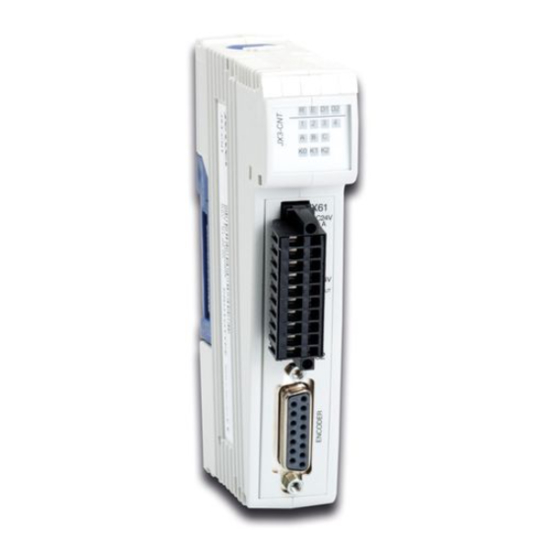
Jetter JX3-CNT Manuals
Manuals and User Guides for Jetter JX3-CNT. We have
1
Jetter JX3-CNT manual available for free PDF download: User Manual
Jetter JX3-CNT User Manual (252 pages)
Counter Module
Brand:
Jetter
| Category:
Control Unit
| Size: 8.2 MB
Table of Contents
Table of Contents
5
1 Safety Instructions
9
Basic Safety Instructions
10
Instructions on EMC
12
2 Product Description and Design
15
Product Description - JX3-CNT
16
Order Reference
17
JX3 Modules: List of Documentation
18
Overview of Features and Interfaces
20
Simultaneous Utilization of Interfaces
23
Minimum Requirements
24
Parts and Interfaces of the JX3-CNT Module
25
Terminal X61 - Internal Block Diagram
26
Female Sub-D Connector X62 - Internal Block Diagram
27
Physical Dimensions
29
3 How to Identify the Module
31
Module Revisions
32
Electronic Data Sheet (EDS) with JC-3Xx
34
Electronic Data Sheet (EDS) with JC-24X
36
Electronic Data Sheet (EDS) with JC-647 and JX6-SB(-I)
38
For Example: Reading out an EDS on a JC-3Xx
40
For Example: Reading out an EDS on a JC-24X
42
Identifying the Module
44
Identification Via Nameplate
45
4 Mounting and Installation Interfaces
48
Interfaces
48
Terminal X61 - Pin Assignment
49
Assignment of Sub-D Connector X62
51
Connector Specification - Terminal X61
53
Sub-D Connector X62 - Specification of Mating Connector
54
Connecting Sensors and Actuators
55
Multi-Purpose I/Os - Special Functions
56
Multi-Purpose I/Os - Special Functions
57
Improving the Noise Immunity
58
Connecting a Single-Channel Counter, 24 V
60
Connecting a Dual-Channel Counter, 24 V
62
Connecting an SSI Encoder
64
Connection of 5 V Incremental Encoders
67
4.2 Indicators and Leds
71
Leds on the Module JX3-CNT
72
4.3 Installing, Replacing, and Removing the Module
75
Installing a JX3 Peripheral Module on a DIN Rail
76
Replacing a JX3 Peripheral Module
77
Removing a JX3 Peripheral Module from the DIN Rail
79
5 Initial Commissioning
81
Preparatory Work for Initial Commissioning
82
Initial Commissioning Along with a JC-3Xx
83
Initial Commissioning Along with a JC-24X
85
6 Programming
87
Abbreviations, Module Register Properties and Formats
88
6.1 Register and I/O Numbering for JX3 Modules
90
Registers and Module Registers
91
I/O Module Numbers in the JX2 System Bus
92
Register and I/O Numbers with JC-24X and JM-D203-JC-24X
93
Register and I/O Numbers with JC-3Xx
94
Register and I/O Numbers for JC-647 with JX6-SB(-I)
95
Register and I/O Numbers for JC-800 with JX6-SB(-I)
96
Register and I/O Numbers for JC-9Xx with JX6-SB(-I)
97
Register Access to JX3 Modules on the JX2 System Bus
98
Direct Register Access to JX3 Modules on the JX2 System Bus
99
Example - Direct Register Access
100
Indirect Register Access to JX3 Modules on the JX2 System Bus
101
Example - Indirect Register Access
103
Module Registers for Indirect Register Access
104
6.3 Address Ranges of Counters
105
Address Ranges of Counters
106
6.4 Zeroing a Counter
108
Zeroing a Counter by Means of Software
109
Zeroing a Counter by Means of Hardware
110
6.5 Multi-Purpose I/Os - Additional Functions
111
Gate Function
112
Gate Function
113
Example: Gate Function
115
Strobe Function
117
Strobe Function
118
Example: Strobe Function
121
Multi-Strobe Function
123
Multi-Strobe Function
124
Multi-Strobe - Description of Registers
127
Example: Multi-Strobe Function
130
Reference Function
132
Reference Function for Single-Channel Counters
133
Example: Reference Function for Single-Channel Counters
135
Reference Function for Dual-Channel Counters
137
Example: Reference Function for Dual-Channel Counters
139
Programming Single-Channel Counters (24 V)
141
Single-Channel Counter I/O1
142
Register Description - Single-Channel Counter I/O1
143
Example - Single-Channel Counter I/O1
145
Single-Channel Counter (Counter A, B, C at X61)
146
Register Description - Single-Channel Counter A, B, C at X61
148
Example: Single-Channel Counter at X61.A
159
6.7 Programming - Dual-Channel Counters
162
Dual-Channel Counter 24 V (X61.A
163
Register Description - Dual-Channel Counter 24 V
164
Dual-Channel Counter
174
Register Description - Dual-Channel Counter 5 V
175
6.8 Ssi
185
Ssi
186
Register Description - SSI
187
Example: SSI
191
6.9 Additional Features
193
Digital I/Os
194
Counter-Controlled Digital Outputs
196
Register Description - Counter Control for Digital Outputs
198
Example - Counter-Controlled Output
204
Monitoring of Limit Values
207
Programming Process Data Pointers
209
Register Description - Process Data Pointers
211
Trailing Indicator
213
Forcing Function (Only SSI Encoder)
215
User-Defined Scaling
216
Operating Principle - User-Defined Scaling Function
217
Configuring the User-Defined Scaling
218
Oscilloscope
220
Start/Stop Recording
221
Continuous Recording
223
Recording Values under Trigger Condition
225
Reading out Recorded Values
228
Oscilloscope Register Description
229
Example: Recording and Reading Values
231
6.10 Monitoring the State by Means of Collective Bits
234
Monitoring the State by Means of Collective Bits
235
7 Quick Reference - JX3-CNT
237
Appendix
241
Technical Data
242
Technical Specifications
243
Physical Dimensions
244
Operating Parameters: Environment and Mechanics
245
Operating Parameters: Enclosure
246
DC Power Supply Inputs and Outputs
247
Shielded Data and I/O Lines
248
B: Index
249
Related Products
Jetter JX3-BN-CAN
jetter JX3-AO4
Jetter JX3-THI2-TC
Jetter JX3-BN-ETH
Jetter JX3-PS1
Jetter JX3-COM-PND
Jetter JX3-COM-EIPA
Jetter JX3-THI2-RTD
Jetter JX3-DMS2
Jetter JX3-THI2-TC-EI
Jetter Categories
Control Unit
Controller
Amplifier
Computer Hardware
Recording Equipment
More Jetter Manuals