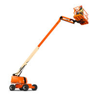
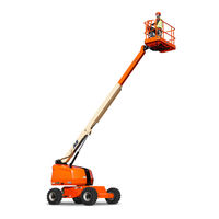
beautypg.com
Manuals
Brands
JLG Manuals
Lifting Systems
460SJ
JLG 460SJ Manuals
Manuals and User Guides for JLG 460SJ. We have
4
JLG 460SJ manuals available for free PDF download: Service And Maintenance Manual, Operation & Maintenance Instructions Manual, Operation And Safety Manual, Operation Manual
JLG 460SJ Service And Maintenance Manual (662 pages)
Brand:
JLG
| Category:
Lifting Systems
| Size: 82.49 MB
Table of Contents
General
3
Bhydraulic System Safety
3
Maintenance
3
Table of Contents
5
Specifications
23
Operating Specifications
23
Capacities
24
Engine Data
24
Tires
25
Hydraulic Oil
25
Mobil DTE 13M Specs
26
Critical Stability Weights
27
Operator Maintenance and Lubrication Diagram - Deutz 2.9L Engine
28
Operator Maintenance and Lubrication Diagram - Deutz 2011L Engine
29
Operator Maintenance and Lubrication Diagram - GM Engine
30
Operator Maintenance and Lubrication Diagram - Kubota Engine
31
Maintenance and Lubrication
32
Torque Chart - Sheet 1 of 5 - (SAE Fasteners)
39
Torque Chart - Sheet 2 of 5 - (SAE Fasteners)
40
Torque Chart - Sheet 3 of 5 - (SAE Fasteners)
41
Torque Chart - Sheet 4 of 5 - (METRIC Fasteners)
42
Torque Chart - Sheet 5 of 5 - (METRIC Fasteners)
43
General
45
Machine Preparation, Inspection, and Maintenance
45
Preparation, Inspection, and Maintenance
45
Pre-Start Inspection
45
Pre-Delivery Inspection and Frequent Inspection
45
Annual Machine Inspection
45
Preventive Maintenance
45
Service and Guidelines
46
General
46
Safety and Workmanship
46
Cleanliness
46
Components Removal and Installation
46
Component Disassembly and Reassembly
47
Pressure-Fit Parts
47
Bearings
47
Gaskets
47
Bolt Usage and Torque Application
47
Hydraulic Lines and Electrical Wiring
47
Hydraulic System
47
Lubrication
47
Battery
47
Lubrication and Servicing
47
Lubrication and Information
48
Hydraulic System
48
Hydraulic Oil
48
Changing Hydraulic Oil
48
Lubrication Specifications
48
Cylinder Drift Test
49
Theory
49
Cylinder Leakage Test
49
Cylinder Thermal Drift
49
Pins and Composite Bearing Repair Guidelines
50
Welding on JLG Equipment
50
Do the Following When Welding on JLG Equipment
50
Do NOT Do the Following When Welding on JLG Equipment
50
Inspection and Preventive Maintenance Schedule
51
Engine Operating Temperature Specifications - Deutz 2.9
54
Engine Operating Temperature Specifications - GM
55
Engine Oil Operating Temperature Specifications - Deutz 2011
56
Engine Operating Temperature Specifications - Kubota
57
Hydraulic Oil Operating Temperature Specifications
58
Chassis & Turntable
59
Tires and Wheels
59
Tire Inflation
59
Tire Damage
59
Tire Replacement
59
Wheel Replacement
59
Wheel Installation
59
Chassis Tilt Indicator System
60
Drive System (4WD & 2WD)
60
Drive Orientation System
60
Lockout Cylinder Bleeding
60
Oscillating Axle System
61
Oscillating Axle Lockout Test
61
Axle Installation
62
Steer Installation (Without Tow Package)
63
Steer Installation (with Tow Package)
64
Wheel Drive Assembly
65
Installation
65
Removal
65
Torque Hub
66
Roll and Leak Testing
66
Tightening and Torquing Bolts
66
Hub-Spindle Disassembly
67
Main Disassembly for "B" Drives
67
Drive Hub and Brake Assembly (2WD and 4WD) - Sheet 1 of 2
68
Drive Hub and Brake Assembly (2WD and 4WD) - Sheet 2 of 2
69
Drive Hub (4WD Front Only) - Sheet 1 of 2
70
Drive Hub (4WD Front Only) - Sheet 2Of 2
71
Drive Hub (Cross-Section)
72
Cover Disassembly
73
Carrier Disassembly
73
Assemble Carrier
73
Cover Sub-Assembly
75
Hub-Spindle Sub-Assembly
76
Main Assembly
78
Cluster Gear Punch Marks
80
Tool List
83
Re-Align Torque Hub Input Coupling
84
Equipment Required
84
Procedure
84
Drive Motor
84
Description
84
Loop Flushing Valve
85
Shaft Seal Replacement
85
Troubleshooting
86
Disassembly
87
End Cap
88
Cylinder Kit
89
Swash Plate & Servo Piston
90
Inspection
91
Assembly
93
Swash Plate and Journal Bearing
94
Cylinder Kit Installation
95
End Cap
96
Initial Start-Up Procedures
97
Swing System
98
Swing Drive Hub
99
Brake Test
99
Brake Leak Repair Procedure
100
Roll and Leak Test
100
Spring Checking Procedure
100
Tightening and Torquing Bolts
101
Lubrication Information
102
Motor Removal
102
Swing Motor Valve Removal
103
Input Brake Disassembly
104
Main Disassembly
105
Housing-Shaft Disassembly
106
Carrier Disassembly
107
Carrier Assembly
108
Housing - Shaft Assembly
109
Main Assembly
110
Motor and Brake Assembly
112
Swing Motor Installation
113
Motor and Brake Assembly
114
Motor Control Valve Installation
115
Bearing Cone Press Tool
116
Bearing Cup Press Tool
117
Lockout Wrench Tool
118
Bearing Cup Press Tool
119
Seal Press Tool
120
Leak Test Adapter Plate
121
Swing Drive Test Plate
122
Swing Motor
123
Disassembly and Inspection
123
Swing Motor Assembly
124
Assembly
130
One Piece Stator Construction
137
Swing Bearing
138
Swing Bearing Wear Tolerance
138
Turntable Bearing Mounting Bolt Condition Check
139
Swing Bearing Installation
143
Swing Bearing Removal
143
Procedure for Setting Swing Gear Backlash
144
Swing Bearing Torque Values
145
Swing Bearing Torque Sequence
146
Rotary Coupling
147
Rotary Coupling Cutaway
148
Rotary Coupling Installation
149
Rotary Coupling Port Location - (SN 0300203771 through 0300222808)
150
Generator
152
Inspecting Brushes, Replacing Brushes and Cleaning Slip Rings
152
Maintenance Schedule
152
Overload Protection
152
Inspecting Generator Brushes, Replacing Brushes and Cleaning Slip Rings
153
Generator Disassembly and Assembly
154
Generator Troubleshooting Circuit Diagram - Sheet 1 of 2
155
Generator Troubleshooting Circuit Diagram - Sheet 2 of 2
156
Power Board PC2 Electrical Circuit Diagram - Sheet 1 of 2
159
Power Board PC2 Electrical Circuit Diagram - Sheet 2 of 2
160
Lead Connection List for Generator
161
Deutz Engine
162
Deutz D2.9L4 Engine Components - Sheet 2 of 2
163
Deutz D2011 Engine Components - Sheet 1 of 3
164
Deutz D2011 Engine Components - Sheet 2 of 3
165
Deutz D2011 Engine Components - Sheet 3 of 3
166
GM Engine
167
GM Engine Components - Sheet 2 of 2
168
Kubota Engine
169
Kubota Engine Components - Sheet 2 of 2
170
Deutz Engine - D2.9L4
171
Check Oil Level
171
Glow Plugs
171
Replacing Engine Oil
171
Replacing the Fuel Filters
172
Replacing the Oil Filter
172
Deutz Engine - D2011
173
Check Oil Level
173
Glow Plugs
173
Replacing Engine Oil
174
Replacing the Oil Filter
175
Replacing the Fuel Filter
176
Deutz EMR 2
177
EMR 2 Engine Plug Pin Identification
182
EMR 2 Vehicle Plug Pin Identification
183
GM Engine General Maintenance
189
Checking/Filling Engine Oil Level
189
Engine Electrical System Maintenance
189
Maintenance of the Drive Belt
189
Changing the Engine Oil
190
Coolant Fill Procedure - Dual Fuel Engine
190
GM Engine Dual Fuel System
191
Fuel Filter
191
Electric Lock off
192
EPR Assembly
192
Low Pressure Regulator (LPR)
192
Air Fuel Mixer
193
Electronic Throttle Control (ETC)
193
Engine Control Module
194
Gasoline Multi Point Fuel Injection System (MPFI)
194
Heated Exhaust Gas Oxygen Sensor
194
Fuel Filter
195
Fuel Injector
195
Fuel Injector Rail
195
Gasoline Fuel Pump
195
Gasoline Pressure and Temperature Sensor Manifold
195
GM Engine Fuel System Repair
196
Propane Fuel System Leak Test
196
Propane Fuel System Pressure Relief
196
Propane Fuel Filter Replacement
197
Electronic Pressure Regulator (EPR) Assembly Replacement
198
Electronic Throttle Control Replacement
199
Mixer Assembly
200
Mixer Replacement
201
Coolant Hose Replacement
201
Vapor Hose Replacement
201
Engine Control Module Replacement
202
Heated Exhaust Gas Oxygen Sensor Replacement
202
GM Engine LPG Fuel System Diagnosis
203
Diagnostic Aids
203
Fuel System Description
203
GM LPG Fuel System Diagnosis
204
GM Engine Symptom Diagnosis
206
DTC to SPN/FMI Cross Reference Chart
214
Deutz Engine Fault Codes
216
Counterweight
273
Boom & Platform
275
Boom Systems
275
Platform Control Enable System
275
Platform Load Sensing System (LSS) (if Equipped)
275
Above Elevation (above Horizontal) - Drive Speed Cutback System
275
Transport Position Interlock System (CE Only)
275
Function Speed Control System
275
Main Boom Lift End of Stroke Dampening
276
Jib Lift End of Stroke Dampening
276
Machine Safety Override (MSSO) (CE Only)
276
Transport Position Sensing System
276
Telescope Retracted Sensors
277
Telescope Retracted Sensors Circuit
278
Transport Proximity Switch Installation
279
Dual Capacity Sensors
280
Dual Capacity Sensors Circuit
281
Capacity Switch Installation
282
Platform
283
Platform/Support Removal
283
Platform/Support Installation
284
Platform Support Torque Values (Without LSS)
285
Platform Support Torque Values (Single Cell LSS)
286
Rotator and Platform Level Cylinder
287
Removal
287
Removal/Installation of Components - Rotator and Platform Level Cylinder
288
Installation
289
Main Boom Powertrack
290
Installation
290
Removal
290
Powertrack Installation
291
Powertrack Maintenance
292
Boom Assembly
301
Removal
301
Disassembly
302
Assembly
303
Inspection
303
Installation
305
Jib (460SJ Only)
306
Assembly
306
Disassembly
306
Inspection
306
Removal
306
Installation
307
Boom Cleanliness Guidelines
307
Boom Shimming Procedure
308
Rotator Assembly
309
Theory of Operation
309
Before Disassembly
310
Making a Seal Tool
310
Required Tools
310
Rotator - Exploded View
311
Rotator - Assembly Drawing
312
Disassembly
313
Inspection
317
Assembly
317
Installing Counterbalance Valve
323
Greasing Thrust Washers
324
Testing the Actuator
324
Installation and Bleeding
325
Skyguard
326
Function Test
326
Operation
326
Diagnostics & Troubleshooting
327
Platform Rotate Bleed Procedure
328
General Notes & Precautions
328
Procedure
328
Bolt-On External Fall Arrest
329
Inspection before Use
329
Installation
329
Bolt-On External Fall Arrest System
331
Basic Hydraulics Information & Schematics
333
Lubricating O-Rings in the Hydraulic System
333
Cup and Brush
333
Dip Method
334
Spray Method
334
Brush-On Method
334
Hydraulic Connection Assembly and Torque Specification
335
Tapered Thread Types
335
Straight Thread Types, Tube and Hose Connections
335
Straight Thread Types, Port Connections
336
Flange Connection Types
336
Tightening Methods
336
Assembly and Torque Specifications
337
Assembly Instructions for American Standard Pipe Thread Tapered (NPTF) Connections
338
Assembly Instructions for British Standard Pipe Thread Tapered (BSPT) Connections
339
Assembly Instructions for 37° (JIC) Flare Fittings
340
Flare (Jic)Thread - Steel
341
Flare (Jic)Thread - Aluminum/Brass
342
Assembly Instructions for 45° SAE Flare Fittings
343
Flare (SAE) - Steel
344
Assembly Instructions for O-Ring Face Seal (ORFS) Fittings
345
O-Ring Face Seal (ORFS) - Aluminum/Brass
346
Assembly Instructions for DIN 24° Flare Bite Type Fittings (MBTL and MBTS)
347
DIN 24°Cone (MBTL & MBTS)
348
Assembly Instructions for Bulkhead (BH) Fittings
349
Bulkhead Fittings (BH) - INCH
350
Bulkhead Fittings (BH) - METRIC
351
Assembly Instructions for O-Ring Boss (ORB) Fittings
352
O-Ring Boss (ORB) - Table 1 of 6
353
O-Ring Boss (ORB) - Table 2 of 6
354
O-Ring Boss (ORB) - Table 3 of 6
355
O-Ring Boss (ORB) - Table 4 of 6
356
O-Ring Boss (ORB) - Table 5 of 6
357
O-Ring Boss (ORB) - Table 6 of 6
358
Assembly Instructions for Adjustable Port End Metric (MFF) Fittings
359
Metric Flat Face Port (MFF) - L Series - Table 1 of 3
360
Metric Flat Face Port (MFF) - L Series - Table 2 of 3
361
Metric Flat Face Port (MFF) - L Series - Table 3 of 3
362
Metric Flat Face Port (MFF) - S Series - Table 1 of 3
363
Metric Flat Face Port (MFF) - S Series - Table 2 of 3
364
Metric Flat Face Port (MFF) - L Series - Table 3 of 3
365
Assembly Instructions for Metric ISO 6149 (MPP) Port Assembly Stud Ends
366
Metric Pipe Parallel O-Ring Boss (MPP)
367
Assembly Instructions for Adjustable Port End (BSPP) Fittings
368
British Standard Parallel Pipe Port (BSPP) - L Series - Table 1 of 3
369
British Standard Parallel Pipe Port (BSPP) - L Series - Table 2 of 3
370
British Standard Parallel Pipe Port (BSPP) - L Series - Table 3 of 3
371
British Standard Parallel Pipe Port (BSPP) - S Series - Table 1 of 3
372
British Standard Parallel Pipe Port (BSPP) - S Series - Table 2 of 3
373
British Standard Parallel Pipe Port (BSPP) - S Series - Table 3 of 3
374
Assembly Instructions for Flange Connections: (FL61 and FL62)
375
Flange Code (FL61 & FL62) -Inch Fasteners
376
Flange Code (FL61 & FL62) - Metric Fasteners
377
Double Wrench Method
378
FFWR and TFFT Methods
379
Adjustable Stud End Assembly
379
O-Ring Installation (Replacement)
380
Hydraulic Cylinders
381
Axle Lockout Cylinder
381
Axle Lockout Cylinder
382
Platform Level Cylinder
383
Platform Level Cylinder
384
Composite Bearing Installation
386
Wiper Seal Installation
387
Jib Lift Cylinder (460SJ Only)
388
Jib Lift Cylinder (460SJ Only)
389
Tapered Bushing Removal
390
Composite Bearing Installation
391
Wiper Seal Installation
392
Hydrolock Piston Seal Installation
393
Main Lift Cylinder (SN 0300203771 through 0300243703, SN E300000100 through E300005607)
394
Main Lift Cylinder (SN 0300203771 through 0300204034)
395
Main Lift Cylinder (SN 0300204035 through 0300226846, SN E300000100 through E3000004457)
396
Main Lift Cylinder (SN 0300226847 through 0300243703, SN E3000004458 through E300005607)
397
Tapered Bushing Removal
398
Composite Bearing Installation
399
Wiper Seal Installation
400
Hydrolock Piston Seal Installation
401
Main Lift Cylinder (SN 0300243704 to Present, SN E300005608 to Present)
402
Main Lift Cylinder (SN 0300243704 to Present, SN E300005608 to Present)
403
Composite Bearing Installation
405
Wiper Seal Installation
406
Master Cylinder
407
Master Cylinder
408
Composite Bearing Installation
410
Wiper Seal Installation
411
Steer Cylinder
412
Steer Cylinder
413
Rod Seal Installation
414
Telescope Cylinder
415
Telescope Cylinder
416
Tapered Bushing Removal
417
Composite Bearing Installation
418
Wiper Seal Installation
419
Piston Seal Kit Installation
420
Pressure Setting Procedure
421
Main System Relief
421
Steer Left Relief
421
Steer Right Relief
422
Swing Relief
422
Jib Lift down Relief (460SJ Only)
423
Platform Level up Relief
423
Platform Level down Relief
424
Main Control Valve Identification (400S) - Sheet 1 of 2
425
Main Control Valve Identification (400S) - Sheet 2 of 2
426
Main Control Valve Identification (460SJ) - Sheet 1 of 2
427
Main Control Valve Identification (460SJ) - Sheet 2 of 2
428
Main Control Valve Torque Values - Sheet 1 of 2
429
Main Control Valve Torque Values - Sheet 2 of 2
430
Drive Pump Pre-Fill Procedure
431
Hydraulic Schematics
432
Hydraulic Schematic - Sheet 2 of 8
433
Hydraulic Schematic - Sheet 3 of 8
434
Hydraulic Schematic - Sheet 4 of 8
435
Hydraulic Schematic - Sheet 5 of 8
436
Hydraulic Schematic - Sheet 6 of 8
437
Hydraulic Schematic - Sheet 7 of 8
438
Hydraulic Schematic - Sheet 8 of 8
439
Jlg Control System
441
JLG Control System Analyzer Kit Instructions
441
Introduction
441
To Connect the JLG Control System Analyzer
442
Using the Analyzer
442
Changing the Access Level of the Hand Held Analyzer
443
Adjusting Parameters Using the Hand Held Analyzer
444
Machine Setup
445
Tilt Sensor Calibration
446
Tilt Sensor Location
448
Ground Control Console Display Gauge
449
Ground Control Console Display Gauge
450
Analyzer Abbreviations
451
Analyzer Connecting Points
453
Ground Control Module - Sheet 1 of 3
454
Ground Control Module - Sheet 2 of 3
455
Ground Control Module - Sheet 3 of 3
456
Platform Module - Sheet 1 of 2
457
Platform Module - Sheet 2 of 2
458
Machine Configuration Programming Information (Software Version P2.10)
459
Machine Configuration Programming Settings - 400S (Software Version P2.10)
465
Machine Configuration Programming Settings - 460SJ (Software Version P2.10)
466
Analyzer Flow Chart - Diagnostics (Software Version P2.10) - Sheet 1 of 4
468
Analyzer Flow Chart - Diagnostics (Software Version P2.10) - Sheet 2 of 4
469
Analyzer Flow Chart - Diagnostics (Software Version P2.10) - Sheet 3 of 4
470
Analyzer Flow Chart - Diagnostics (Software Version P2.10) - Sheet 4 of 4
471
Analyzer Flow Chart - Personalities (Software Version P2.10) - Sheet 1 of 2
472
Analyzer Flow Chart - Personalities (Software Version P2.10) - Sheet 2 of 2
473
Analyzer Flow Chart - Machine Setup (Software Version P2.10)
474
Analyzer Flow Chart - Calibrations (Software Version P2.10)
475
LSS System
476
Diagnostic Menu
477
Calibration Procedure
478
Accessory Weights
479
Skyglazier Capacity Reductions
481
Testing & Evaluation
483
Troubleshooting
484
Resetting the MSSO System
485
Machine Model Adjustment
487
Adjustment Notes
487
Machine Orientation When Performing Test
487
Machine Model Adjustment Speeds
490
Diagnostic Trouble Code Chart
492
Basic Electrical Information & Schematics
531
General
531
Multimeter Basics
531
Grounding
531
Backprobing
531
Min/Max
531
Polarity
531
Scale
531
Voltage Measurement
531
Resistance Measurement
532
Continuity Measurement
532
Current Measurement
533
Applying Silicone Dielectric Compound to Electrical Connections
533
Installation of Dielectric Grease
534
Deutsch HD, DT, DTM, DRC Series
534
AMP Seal
534
AMP Mate-N-Lok
535
DIN Connectors
535
Exclusions
536
Brad Harrison / Phoenix Contact M12
536
Engine Control Unit Connectors
536
Sealed Enclosures
536
MIL-C-5015 Spec Connectors
537
MOLEX CMC Series Connectors
537
AMP Connector
538
Assembly
538
Connector Assembly Figure 2
539
Disassembly
540
Wedge Lock
540
Service - Voltage Reading
540
Connector Installation
541
Deutsch Connectors
542
DT/DTP Series Assembly
542
DT/DTP Series Disassembly
542
HD30/HDP20 Series Assembly
543
HD30/HDP20 Series Disassembly
543
Telematics Gateway
544
Telematics-Ready (TCU) Plug
544
Telematics Gateway Harness - Sheet 2 of 3
546
Telematics Gateway Harness - Sheet 3 of 3
547
Electrical Installation - Sheet 1 of 5
548
Electrical Installation - Sheet 2 of 5
549
Electrical Installation - Sheet 3 of 5
550
Electrical Installation - Sheet 4 of 5
551
Electrical Installation - Sheet 5 of 5
552
Wiring Harness Connector Labels and Wiring Harnesses
553
Component Labels
553
Connector Labels
553
Platform Control Box Harness - Sheet 3 of 12
557
Platform Control Box Harness - Sheet 4 of 12
558
Platform Control Box Harness - Sheet 5 of 12
559
Platform Control Box Harness - Sheet 7 of 12
561
Platform Control Box Harness - Sheet 8 of 12
562
Platform Control Box Harness - Sheet 9 of 12
564
Platform Control Box Harness - Sheet 10 of 12
565
Platform Control Box Harness - Sheet 11 of 12
566
Turntable Harness - Sheet 2 of 14
574
Turntable Harness - Sheet 3 of 14
575
Turntable Harness - Sheet 5 of 14
577
Turntable Harness - Sheet 6 of 14
578
Turntable Harness - Sheet 7 of 14
579
Turntable Harness - Sheet 8 of 14
580
Turntable Harness - Sheet 9 of 14
581
Turntable Harness - Sheet 10 of 14
582
Turntable Harness - Sheet 12 of 14
585
Turntable Harness - Sheet 13 of 14
586
Main Valve Harness - Sheet 3 of 7
591
Main Valve Harness - Sheet 4 of 7
592
Main Valve Harness - Sheet 6 of 7
595
Main Valve Harness - Sheet 7 of 7
596
Ground Control Panel Harness - Sheet 2 of 5
599
Ground Control Panel Harness - Sheet 5 of 5
602
Deutz T4I Harness - Sheet 2 of 4
605
Deutz T4I Harness - Sheet 4 of 4
607
Deutz T4F Harness - Sheet 3 of 11
610
Deutz T4F Harness - Sheet 2 of 11
611
Deutz T4F Harness - Sheet 4 of 11
612
Deutz T4F Harness - Sheet 5 of 11
613
Deutz T4F Harness - Sheet 6 of 11
614
Deutz T4F Harness - Sheet 7 of 11
615
Deutz T4F Harness - Sheet 8 of 11
616
Deutz T4F Harness - Sheet 9 of 11
617
Deutz T4F Harness - Sheet 10 of 11
618
GM Engine Harness - Sheet 2 of 2
621
Skyguard Harness - Sheet 1 of 2
622
Skyguard Harness - Sheet 2 of 2
623
Cribbing Enable Harness
624
Chassis Head and Tail Lights Harness - Sheet 2 of 3
627
Chassis Head and Tail Lights Harness - Sheet 3 of 3
628
Chassis Work Lights Harness - Sheet 2 of 3
631
Chassis Work Lights Harness - Sheet 3 of 3
632
Electrical Schematics
633
Electrical Schematic - Sheet 2 of 25
634
Electrical Schematic - Sheet 3 of 25
635
Electrical Schematic - Sheet 4 of 25
636
Electrical Schematic - Sheet 5 of 25
637
Electrical Schematic - Sheet 6 of 25
638
Electrical Schematic - Sheet 7 of 25
639
Electrical Schematic - Sheet 8 of 25
640
Electrical Schematic - Sheet 9 of 25
641
Electrical Schematic - Sheet 10 of 25
642
Electrical Schematic - Sheet 11 of 25
643
Electrical Schematic - Sheet 12 of 25
644
Electrical Schematic - Sheet 13 of 25
645
Electrical Schematic - Sheet 14 of 25
646
Electrical Schematic - Sheet 15 of 25
647
Electrical Schematic - Sheet 16 of 25
648
Electrical Schematic - Sheet 17 of 25
650
Electrical Schematic - Sheet 18 of 25
651
Electrical Schematic - Sheet 19 of 25
652
Electrical Schematic - Sheet 20 of 25
653
Electrical Schematic - Sheet 21 of 25
654
Electrical Schematic - Sheet 22 of 25
656
Electrical Schematic - Sheet 23 of 25
657
Electrical Schematic - Sheet 24 of 25
658
Electrical Schematic - Sheet 25 of 25
659
JLG 460SJ Operation And Safety Manual (145 pages)
Brand:
JLG
| Category:
Construction Equipment
| Size: 28.35 MB
Table of Contents
Table of Contents
8
Section 1 - Safety Precautions
14
General
14
Pre-Operation
14
Operator Training and Knowledge
14
Workplace Inspection
15
Machine Inspection
16
Operation
16
General
16
Trip and Fall Hazards
17
Electrocution Hazards
18
Minimum Approach Distances (M.A.D.)
19
Tipping Hazards
20
Beaufort Scale (for Reference Only)
22
Crushing and Collision Hazards
23
Towing, Lifting, and Hauling
24
Maintenance
24
Maintenance Hazards
24
Battery Hazards
25
Section 2 - User Responsibilities, Machine Preparation, and Inspection
26
2.1 Personnel Training
26
Operator Training
26
Training Supervision
26
Operator Responsibility
27
Machine Familiarization
27
2.2 Preparation, Inspection, and Maintenance
27
Inspection and Maintenance Table
28
Basic Nomenclature
29
Pre-Start Inspection
30
Walk-Around Inspection
32
Function Check
35
Skyguard Function Test
36
Oscillating Axle Lockout Test (if Equipped)
37
Section 3 - Machine Controls and Indicators
39
General
39
Controls and Indicators
39
Ground Control Console - 400S
40
Ground Control Console - 400S W/Msso (CE Only)
41
Ground Control Console - 460SJ
42
Ground Control Console - 460SJ W/Msso (CE Only)
43
Ground Control Console
44
Ground Control Indicator Panel
47
Ground Control Indicator Panel
48
Ground Control Console Display Gauge
50
Splash Screen
50
Diagnostic Screen
51
Engine Diagnostic Screen
51
Ground Control Console Display Gauge
52
Platform Control Console
53
Platform Console
54
Platform Control Indicator Panel
59
Section 4 - Machine Operation
63
Description
63
Boom Operating Characteristics and Limitations
63
Capacities
63
Platform Load Sensing System (LSS)
64
Stability
64
Position of Least Forward Stability
65
Position of Least Backward Stability
66
Engine Operation
67
Starting Procedure
67
Shutdown Procedure
68
Fuel Reserve / Shut-Off System (Diesel Engines Only)
69
Grade and Side Slopes
70
Traveling (Driving)
71
Traveling Forward and Reverse
72
Traveling on a Grade
73
Steering
73
Platform
73
Platform Level Adjustment
73
Platform Rotation
73
Boom
74
Swinging the Boom
74
Raising and Lowering the Main Boom
74
Telescoping the Main Boom
74
Function Speed Control
75
Machine Safety System Override (Msso)
75
(Ce Only)
75
4.10 Skyguard Operation
75
Skyguard
76
Skyguard - Skyline
76
Skyguard - Skyeye
76
Skyguard Function Table
77
Shut down and Park
78
4.12 Lifting and Tie down
78
Lifting
78
Tie down
78
Lifting and Tie down Chart
79
Decal Legend - 400S
87
Decal Legend - 460SJ
90
Section 5 - Emergency Procedures
93
General
93
Incident Notification
93
Emergency Operation
93
Operator Unable to Control Machine
93
Platform or Boom Caught Overhead
94
Emergency Towing Procedures
94
Machines
94
Machine Safety System Override (Msso)
95
(Ce Only)
95
Section 6 - Accessories
97
Available Accessories
97
Options/Accessories Relationship Table
98
Fall Arrest
99
Safety Precautions
99
Pipe Racks
99
Capacity Specifications (Australia Only)
100
Safety Precautions
100
Preparation and Inspection
100
Operation
100
Skyglazier
101
Capacity Specifications
101
Safety Precautions
102
Preparation and Inspection
102
Operation
102
Skypower
103
Generator Output
103
Accessory Ratings
103
Safety Precautions
104
Preparation and Inspection
104
Operation
104
Skywelder
104
Accessory Ratings
105
Generator Output
105
Welding Accessories
105
Safety Precautions
106
Preparation and Inspection
106
Operation
106
Soft Touch
107
Bolt-On External Fall Arrest
107
Inspection before Use
108
Bolt-On External Fall Arrest Cable Tension
108
Bolt-On External Fall Arrest System
109
Section 7 - General Specifications & Operator Maintenance
111
Introduction
111
Operating Specifications
111
Operating Specifications - 400S
111
Operating Specifications - 460SJ
112
Capacities
113
Engine Data
113
Deutz D2011L03
113
Deutz D2.9L4
114
Kubota WG 2503
114
Tires
115
Hydraulic Oil
115
Mobilfluid 424 Specs
116
Mobil DTE 10 Excel 32 Specs
116
Mobil EAL 224H Specs
117
Mobil EAL H 46 Specs
118
Exxon Univis HVI 26 Specs
118
Critical Stability Weights
119
Tires
119
Serial Number Location
120
Hydraulic Oil
121
Engine Oil Operation Chart - Kubota
124
Operator Maintenance and Lubrication Diagram
125
Operator Maintenance and Lubrication Diagram
126
Operator Maintenance and Lubrication Diagram
127
Operator Maintenance
128
Lubrication Specifications
128
Tires & Wheels
139
Tire Damage
139
Tire Replacement
140
Wheel Replacement
140
Wheel Installation
140
Wheel Torque Chart
141
Propane Fuel Filter Replacement (Kubota Engine)
142
Removal
142
Installation
143
JLG 460SJ Operation & Maintenance Instructions Manual (164 pages)
Brand:
JLG
| Category:
Boom Lifts
| Size: 7.57 MB
Table of Contents
Table of Contents
7
Section 1 - Safety Precautions
15
General
15
Pre-Operation
15
Operator Training and Knowledge
15
Workplace Inspection
16
Machine Inspection
17
Operation
17
General
17
Trip and Fall Hazards
18
Electrocution Hazards
19
Tipping Hazards
21
Crushing and Collision Hazards
24
Towing, Lifting, and Hauling
25
Maintenance
25
Maintenance Hazards
25
Battery Hazards
27
Section 2. User Responsibilities, Machine Preparation, and Inspection
29
2.1 Personnel Training
29
Operator Training
29
Training Supervision
29
Operator Responsibility
29
2.2 Preparation, Inspection, and Maintenance
30
Pre-Start Inspection
33
Daily Walk-Around Inspection
34
Function Check
36
Skyguard Function Test
37
Oscillating Axle Lockout Test (if Equipped)
38
Section 3 - Machine Controls and Indicators
39
General
39
Controls and Indicators
39
Ground Control Console
40
Ground Control Indicator Panel
47
Ground Control Console Display Gauge
51
Platform Console
54
Platform Control Indicator Panel
60
Section 4 - Machine Operation
65
Description
65
Boom Operating Characteristics and Limitations
66
Capacities
66
Stability
66
Engine Operation
66
Starting Procedure
66
Shutdown Procedure
68
Fuel Reserve / Shut-Off System
68
Traveling (Driving)
71
Traveling Forward and Reverse
73
Traveling on a Grade
74
Steering
74
Platform
74
Platform Level Adjustment
74
Platform Rotation
74
Boom
75
Swinging the Boom
75
Raising and Lowering the Main Boom
75
Telescoping the Main Boom
75
Function Speed Control
76
Machine Safety System Override (Msso)(Ce Only)
76
4.10 Skyguard Operation
77
Skyguard
77
Skyguard - Skyline
77
Skyguard - Skyeye
78
Skyguard Function Table
78
Shut down and Park
79
4.12 Lifting and Tie down
79
Lifting
79
Tie down
80
Section 5 - Emergency Procedures
101
General
101
Incident Notification
101
Emergency Operation
101
Operator Unable to Control Machine
101
Platform or Boom Caught Overhead
102
Emergency Towing Procedures
102
Machine Safety System Override (Msso)(Ce Only)
103
Section 6 - Accessories
105
Fall Arrest
107
Safety Precautions
107
Pipe Racks
107
Capacity Specifications (Australia Only)
108
Safety Precautions
108
Preparation and Inspection
108
Operation
108
Skyglazier
109
Capacity Specifications
109
Safety Precautions
110
Preparation and Inspection
110
Operation
110
Skypower
111
Generator Output
111
Accessory Ratings
111
Safety Precautions
112
Preparation and Inspection
112
Operation
112
Skywelder
112
Accessory Ratings
113
Generator Output
113
Welding Accessories
113
Safety Precautions
114
Preparation and Inspection
114
Operation
114
Soft Touch
115
Bolt-On External Fall Arrest
115
Inspection before Use
116
Section 7 - General Specifications & Operator Maintenance
119
Introduction
119
Operating Specifications
119
Capacities
121
Engine Data
122
Tires
124
Hydraulic Oil
125
Critical Stability Weights
128
Serial Number Location
129
Operator Maintenance
140
Tires & Wheels
154
Tire Inflation
154
Tire Damage
154
Tire Replacement
154
Wheel Replacement
155
JLG 460SJ Operation Manual (140 pages)
boom lift
Brand:
JLG
| Category:
Lifting Systems
| Size: 4.52 MB
Table of Contents
Table of Contents
7
Section 1. Safety Precautions
15
General
15
Pre-Operation
15
Operator Training and Knowledge
15
Workplace Inspection
16
Machine Inspection
17
Operation
17
General
17
Trip and Fall Hazards
18
Electrocution Hazards
19
Tipping Hazards
21
Crushing and Collision Hazards
24
Towing, Lifting, and Hauling
25
Maintenance
25
Maintenance Hazards
25
Battery Hazards
27
Section - 2 - User Responsibilities, Machine Preparation
29
And Inspection
29
2.1 Personnel Training
29
Operator Training
29
Training Supervision
29
Operator Responsibility
29
2.2 Preparation, Inspection, and Maintenance
30
Pre-Start Inspection
32
Function Check
33
Skyguard Function Test
34
General
37
Oscillating Axle Lockout Test (if Equipped)
39
Section 3 - Machine Controls and Indicators
41
General
41
Controls and Indicators
41
Ground Control Console
42
Ground Control Indicator Panel
49
Ground Control Console Display Gauge
52
Platform Console
55
Platform Control Indicator Panel
61
Section 4 - Machine Operation
65
Description
65
Boom Operating Characteristics and Limitations
66
Capacities
66
Stability
66
Engine Operation
66
Starting Procedure
66
Shutdown Procedure
68
Fuel Reserve / Shut-Off System
68
Traveling (Driving)
71
Traveling Forward and Reverse
73
Traveling on a Grade
74
Steering
74
Platform
74
Platform Level Adjustment
74
Platform Rotation
74
Boom
75
Swinging the Boom
75
Raising and Lowering the Main Boom
75
Telescoping the Main Boom
75
Function Speed Control
76
Machine Safety System Override
76
4.10 Skyguard Operation
77
Shut down and Park
78
4.12 Lifting and Tie down
78
Lifting
78
Tie down
79
Section 5 - Emergency Procedures
97
General
97
Incident Notification
97
Emergency Operation
97
Operator Unable to Control Machine
97
Platform or Boom Caught Overhead
98
Emergency Towing Procedures
98
Machine Safety System Override
99
Section 6 - General Specifications & Operator Maintenance
101
Introduction
101
Operating Specifications
101
Capacities
103
Engine Data
104
Tires
105
Hydraulic Oil
106
Critical Stability Weights
109
Serial Number Location
110
Operator Maintenance
119
Tires & Wheels
130
Tire Inflation
130
Tire Damage
130
Tire Replacement
130
Wheel Replacement
131
Wheel Installation
131
Propane Fuel Filter Replacement
133
Removal
133
Installation
133
Propane Fuel System Pressure Relief
134
Supplemental Information
135
Related Products
JLG 4394RT
JLG 400S
JLG 400SJ
JLG 41AM
JLG 4017
JLG 4013PS
JLG 4014PS
JLG 4017PS
JLG 40RTS
JLG 4108AN
JLG Categories
Boom Lifts
Lifting Systems
Scissor Lifts
Construction Equipment
Forklifts
More JLG Manuals