beautypg.com
Manuals
Brands
KAESER Manuals
Air Compressor
M135 SIGMA CONTROL MOBIL
KAESER M135 SIGMA CONTROL MOBIL Manuals
Manuals and User Guides for KAESER M135 SIGMA CONTROL MOBIL. We have
1
KAESER M135 SIGMA CONTROL MOBIL manual available for free PDF download: Service Manual
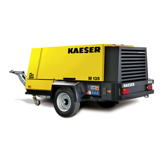
KAESER M135 SIGMA CONTROL MOBIL Service Manual (288 pages)
Screw Compressor
Brand:
KAESER
| Category:
Air Compressor
| Size: 14.43 MB
Table of Contents
Table of Contents
3
1 Regarding this Document Using the Document
13
Further Documents
13
Copyright
13
Symbols and Markings
13
Warning Notices
13
Other Notices and Symbols
14
Tab. 1 the Levels of Danger and Their Meaning
14
2 Technical Specification Nameplate
15
List of Options
15
Tab. 2 Nameplate
15
Compressed Air Distributor
16
Compressed Air Treatment Plant
16
Tab. 3 Combined Label for Coupling Load and Options Fitted
16
Tab. 4 Compressed Air Treatment Plant
16
Tab. 5 Compressed Air Distributor
16
Chassis
17
Check Valve Function
17
Lighting
17
Low Temperature Equipment
17
Tab. 6 Check Valve Function
17
Tab. 7 Low Temperature Equipment
17
Tab. 8 Chassis
17
Pedestrian Protection
18
Machine (Without Options)
18
Sound Emission
18
Tab. 9 Lighting
18
Tab. 10 Pedestrian Protection
18
Tab. 11 Guaranteed Sound Power Level
18
Tab. 12 Emission Sound Pressure Level
18
Tab. 13 Guaranteed Sound Pressure Level
18
Torques
19
Ambient Conditions
19
Additional Specifications
19
Chassis
19
Weights
19
Tab. 14 Torques for Hex-Head Screws
19
Tab. 15 Ambient Conditions
19
Tyres
20
Wheel Nut/Bolt Tightening Torque
20
Towbar Tightening Torque
20
Compressor
20
Working Pressure and FAD
20
Tab. 16 Machine Weights
20
Tab. 17 Tyres
20
Tab. 18 Wheel Nut/Bolt Tightening Torque
20
Tab. 19 Towbar Tightening Torque
20
Tab. 20 Working Pressure and FAD
20
Compressed Air Outlet
21
Pressure Relief Valve
21
Temperature
21
Cooling Oil Recommendation
21
Tab. 21 Compressed Air Distributor
21
Tab. 22 Relief Valve Activating Pressure
21
Tab. 23 Machine Temperatures
21
Cooling Oil Charge
22
Engine
22
Engine Specification
22
Tab. 24 Cooling Oil Recommendation
22
Tab. 25 Cooling Oil Charge
22
Tab. 26 Engine Specification
22
Oil Recommendation
23
Engine Coolant Recommendation
23
Fluid Volumes
23
Batteries
23
Tab. 27 Engine Oil Recommendation
23
Tab. 28 Engine Fluid Volumes
23
Options
24
Low Temperature Equipment
24
Tab. 29 Batteries
24
Tab. 30 Ambient Conditions
24
Tab. 31 Batteries
24
Tab. 32 Coolant Pre-Heater
24
Generator
25
Tab. 33 Generator Data
25
Tab. 34 Delivery in Generator Mode
25
Tab. 35 Connection Sockets
26
Tab. 36 Overload Protection Switch
26
Tab. 37 Generator Operating Limits
26
Tab. 38 Maximum Three-Phase Mains Loading
27
Tab. 39 Maximum Single-Phase Mains Loading
27
3 Safety and Responsibility Basic Information
28
Specified Use
28
Improper Use
28
User's Responsibilities
28
Observe Statutory and Universally Accepted Regulations
28
Defining Personnel
29
Adherence to Inspection Schedules and Accident Prevention Regulations
29
Dangers
30
Safely Dealing with Sources of Danger
30
Tab. 40 Inspection Intervals According to Regulations
30
Safe Machine Operation
32
Organisational Measures
34
Danger Areas
35
Safety Devices
35
Safety Signs
35
Fig. 1 Location of Safety Signs
35
Tab. 41 Danger Areas
35
Tab. 42 Safety Signs
36
Generator Operation
37
Protection against Dangerous Electric Current
37
Instructions for Safe Generator Operation
37
Connection of Extension Cables
37
Maximum Power Supply Loading
37
Regular Generator Inspections
38
Emergencies
38
Correct Fire Fighting
38
Contact with Operating Fluids/Materials
38
Warranty
39
Environmental Protection
39
4 Design and Function Bodywork
40
Fig. 2 Bodywork
40
Component Identification
41
Machine Function
41
Fig. 3 Right-Hand Door Opened
41
Fig. 4 Left-Hand Door Opened
41
Fig. 5 General Design
42
Operating Modes and Control Modes
43
Operating Modes
43
MODULATING Control Mode
43
Safety Devices
44
Monitoring Functions with Shutdown
44
Further Safety Devices
44
Fig. 6 Stepless Regulation of FAD (Standstill)
44
SIGMA CONTROL MOBIL Keys and Displays
45
Fig. 7 Instrument Panel Keys and Displays
45
Tab. 43 Instrument Panel Keys and Displays
45
SIGMA CONTROL MOBIL Function
46
Display
46
Fig. 8 Opening Page
46
Fig. 9 Engine Preheating
47
Fig. 10 Display of Operating Mode (Example)
47
Tab. 44 Display of Messages Prior to Starting
47
Tab. 45 Operating Mode Display
48
Tab. 46 Display of Operational State
48
SIGMA CONTROL MOBIL Operating Sequence
49
Menu Structure of the SIGMA CONTROL MOBIL
50
Tab. 47 SIGMA CONTROL MOBIL Operating Sequence
50
Tab. 48 Menu Structure of the SIGMA CONTROL MOBIL
50
List of Menus
51
Fig. 11 Menu Structure of the SIGMA CONTROL MOBIL
51
Tab. 49 Settings Menu
51
Tab. 50 Menu Selection
52
Tab. 51 Menu Option List
52
Tab. 52 Navigation (Menu)
52
SIGMA CONTROL MOBIL Main Menu
53
Fig. 12 Machine Data Symbol
53
Tab. 53 Symbolic Display of Engine Oil Pressure
53
SIGMA CONTROL MOBIL Settings Menu
54
Tab. 54 Engine Data Display
54
Tab. 55 Display of Compressor Operating Data
54
Tab. 56 Password Level
55
Tab. 57 Menu Guidance
55
Fig. 13 Symbolic Settings Menu
56
SIGMA CONTROL MOBIL Event Memory
57
Fig. 14 Event Memory
57
Tab. 58 Event Memory Outline
58
Fig. 15 Event Memory Example: Alarm Message
59
Fig. 16 Event Memory Example: Warning Message
59
Fig. 17 Event Memory Example: Maintenance Message
59
Air Treatment Options
60
Fig. 18 Message Code Structure
60
Tab. 59 Message Code Structure
60
Air Cooler
61
Cyclone Separator
61
Heat Exchanger
61
Filter Combination
61
Fig. 19 Air Treatment Options
61
Breathing Air Filter
62
Low Temperature Equipment Option
62
Fig. 20 Coolant Pre-Heating
62
Generator Option
63
Operating Modes
63
Operating Controls
63
Tab. 60 Generator/Compressor Operation
63
Tab. 61 Generator Operating Modes
63
Note When Operating the Generator
64
Fig. 21 Generator Instrument Panel - Control Box, 400 V, 3-Phase
64
Fig. 22 Generator Instrument Panel - Control Box, 230 V, 3-Phase
64
Transport Options
65
Chassis
65
Stationary Frame
66
Pedestrian Protection Option
66
5 Installation and Operating Conditions
67
Safety
67
Positioning Conditions
67
Fig. 23 Minimum Distance from Excavations/Slopes and Walls
67
6 Installation Safety
69
Reporting Transport Damage
69
Fitting the Towbar
69
Adjusting the Chassis
70
Fig. 24 Fitting the Towbar
70
Fig. 25 Fitting the Towbar
70
Adjusting the Towbar Height
71
Changing the Towing Eye
71
Fig. 26 Towbar Height Adjustment
71
Fig. 27 Changing the Towing Eye (Height-Adjustable Towbar)
72
Fig. 28 Changing the Towing Eye (Fixed Height Towbar, GB Chassis Version)
73
Fig. 29 Changing the Towing Eye (Fixed Height Towbar, USA Chassis Version)
73
7 Initial Start-Up Safety
75
Instructions to be Observed before Commissioning or Recommissioning
75
Checking Installation and Operating Conditions
75
Tab. 62 Installation and Operating Conditions Checklist
75
Setting the Displayed Units
76
Fig. 30 Temperature Display Setting
76
Entering a Password
77
Fig. 31 Unit of Pressure Setting
77
Fig. 32 Waiting for Password Entry
77
Engine Settings
78
Fig. 33 Password Level 1 Activated
78
Fig. 34 Engine Settings Menu
79
Changing the Parameters of the Start/Stop/Automatic Option
80
Fig. 35 Settings in Start/Stop/Automatic
81
After Storing the Machine for a Long Period
82
Low-Temperature Operation (Winter)
82
Starting Assistance
82
Tab. 63 Measures for Re-Commissioning the Compressor after a Long Period of Storage
82
Fig. 36 Jumper Cable Connection Diagram
83
Starting up Low-Temperature Equipment
84
Putting the Generator into Operation
85
Fig. 37 Coolant Pre-Heating
85
Fig. 38 Insulation Monitoring - 400 V, 3-Phase Generator
85
Fig. 39 Insulation Monitoring - 230 V, 3-Phase Generator
86
Tab. 64 Test Instructions for a Generator with an Insulation Monitoring
86
8 Operation Safety
87
Starting and Stopping
87
Follow the Brief Instructions
87
Fig. 40 Starting Instruments
87
Commissioning the Machine
88
Fig. 41 Brief Instructions on Starting and Stopping
88
Fig. 42 "Battery Isolating Switch
88
Starting the Engine
89
Setting the Output Pressure
89
Fig. 43 Select Menu Option "Set Pressure in the Oil Separator Tank
90
Fig. 44 Setting the Output Pressure
90
Shutting down the Machine
91
Shutting down in an Emergency
92
Setting Parameters
92
Acknowledging Alarm, Warning and Maintenance Messages
92
Displaying Machine Operating Data
93
Using the External Fuel Pump Option
94
Fig. 45 Operating Data Menu
94
Using the Low-Temperature Equipment
95
Generator Operation
95
Fig. 46 External Fuel Pump Switch-On Symbol
95
Switching in the Generator
96
Switching off the Generator
96
9 Fault Recognition and Rectification
97
Basic Instructions
97
SIGMA CONTROL MOBIL Messages
97
Alarm Messages on the Controller (Machine Off)
97
Tab. 65 Fault Messages and Actions Concerning the Engine
98
Tab. 66 Fault Messages and Actions Concerning the Compressor Unit
99
Tab. 67 Fault Messages and Actions Concerning the Controller
99
Warning Message on the Controller
100
Tab. 68 General Fault Messages and Measures
100
Tab. 69 Warning Messages and Measures Relating to the Engine
101
Tab. 70 Warning Messages and Measures Relating to the Compressor
101
Engine Faults and Alarms
102
Engine Refuses to Start or Does Not Turn over
102
Tab. 71 General Warning Messages and Measures
102
Engine Does Not Reach Full Speed
103
Compressor Faults and Alarms
103
Working Pressure too High
103
Tab. 72 Fault: Engine Refuses to Start or Comes to a Stop
103
Tab. 73 Fault: Engine Does Not Reach Full Speed
103
Working Pressure too Low
104
Pressure Relief Valve Blowing off
104
Tab. 74 Fault: Working Pressure too High
104
Tab. 75 Fault: Working Pressure too Low
104
Tab. 76 Fault: Pressure Relief Valve Blowing off
104
Machine Overheating
105
Too Much Oil Residue in the Compressed Air
105
Tab. 77 Fault: Machine Overheating
105
Tab. 78 Fault: too Much Oil Residue in the Compressed Air
105
Oil Flows from the Compressor Air Filter after Shutdown
106
High Moisture Content in the Compressed Air
106
Generator Faults and Alarms
106
There Is no Voltage or too Low a Voltage from the Generator
106
Tab. 79 Fault: Oil Flows from the Compressor Air Filter after Shutdown
106
Tab. 80 Fault: High Moisture Content in the Compressed Air
106
Generator Voltage too High
107
Tab. 81 There Is no Voltage or too Low a Voltage from the Generator
107
Tab. 82 Generator Voltage too High
107
10 1 Maintenance
108
Safety
108
Maintenance Message on the Controller
108
Maintenance Schedules
109
Logging Maintenance Work
109
Maintenance Tasks after Commissioning
109
Tab. 83 Maintenance Messages and Measures Connected with Engine Maintenance
109
Tab. 84 Maintenance Messages and Measures Connected with Compressor Maintenance
109
Regular Maintenance Tasks
110
Tab. 85 Maintenance Tasks after Commissioning
110
Tab. 86 Maintenance Intervals and Regular Maintenance Tasks
110
Tab. 87 Regular Maintenance Tasks
113
Engine
114
Tab. 88 Regular Maintenance Tasks for Options
114
Radiator Maintenance
115
Fig. 47 Checking Coolant Level
116
Tab. 89 KAESER Coolant Mixture Table
117
Fig. 48 Draining the Coolant from the Radiator
118
Fig. 49 Radiator with Centralised Drainage
119
Air Filter Maintenance
120
Fig. 50 Engine Air Filter Maintenance
120
Fig. 51 Cleaning the Filter Element
121
Fig. 52 Fuel System Maintenance
122
Fuel System Maintenance
122
Fig. 53 Warning Indication: Fuel Filter Water Level
123
Fig. 54 Emptying the Fuel Prefilter Water Trap
124
Fig. 55 Changing the Fuel Prefilter Cartridge
124
Fig. 56 Fuel Filter Maintenance
125
Checking the Engine Oil Level
126
Engine Oil Filling and Topping up
126
Fig. 57 Checking the Engine Oil Level
126
Changing the Engine Oil
127
Fig. 58 Draining the Engine Oil
128
Changing the Oil Filter
129
Fig. 59 Draining the Engine Oil, Central Drain Point
129
Checking the Drive Belts
130
Fig. 60 Changing the Oil Filter
130
Fig. 61 Belt Tension Checking by Hand
131
Battery Maintenance
132
Fig. 62 Safety Signs - Warning Stickers on the Battery
132
Compressor
135
Checking Cooling Oil Level
135
Fig. 63 Checking Cooling Oil Level
135
Cooling Oil Filling and Topping up
136
Changing the Cooling Oil
136
Fig. 64 Changing the Cooling Oil
137
Fig. 65 Central Compressor Oil Drainage
138
Changing the Oil Filter
139
Fig. 66 Changing the Oil Filter
140
Oil Separator Tank Dirt Trap Maintenance
141
Fig. 67 Cleaning the Dirt Trap
141
Changing the Oil Separator Cartridge
142
Fig. 68 Changing the Oil Separator Cartridge
142
Air Filter Maintenance
143
Fig. 69 Compressor Air Filter Maintenance
144
Fig. 70 Cleaning the Filter Element
144
Checking Pressure Relief Valves
145
Cleaning the Coolers and Radiator
145
Fig. 71 Cooler/Radiator Cleaning
146
Cleaning the Compressed Air Aftercooler
147
Fig. 72 Cleaning the Compressed Air Aftercooler
147
Rubber Sealing Strip Maintenance
148
Chassis
148
Wheel Checks
148
Towbar Maintenance
148
Fig. 73 Overrun Braking Mechanism Maintenance
149
Brake Maintenance
150
Fig. 74 Ball Coupling Maintenance
150
Fig. 75 Ball Coupling Maintenance (USA Version)
150
Fig. 76 Checking the Brake Lining Thickness
151
Fig. 77 Brake Adjustment
152
Options
153
Cyclone Separator Maintenance
153
Fig. 78 Cleaning the Dirt Trap
153
Combination Filter Maintenance
154
Fig. 79 Combination Filter Maintenance
155
Breathing Air Filter Maintenance
157
Fig. 80 Breathing Air Filter Maintenance
157
Generator Drive Belt Maintenance
159
Fig. 81 Generator Belt Tensioning
159
Document Maintenance and Service Work
162
Tab. 90 Logged Maintenance Tasks
162
11 Spares, Operating Materials, Service
163
Note the Nameplate
163
Ordering Consumable Parts and Operating Materials
163
Tab. 91 Compressor Consumables
163
Tab. 92 Consumable Engine Parts
163
Kaeser Air Service
164
Service Addresses
164
12 Decommissioning, Storage and Transport
165
Commissioning
165
Temporary Decommissioning
165
Tab. 93 "Temporarily Decommissioned" Information Notice
165
Long-Term Decommissioning
166
Tab. 94 Long-Term Decommissioning Checklist
166
Transporting
167
Towing the Compressor on the Road
167
Tab. 95 Text for the Long-Term Decommissioned Information Notice
167
Fig. 82 Towing Alignment
168
Fig. 83 Ball Coupling (ALKO-EU)
169
Fig. 84 Ball Coupling (ALKO-USA)
170
Fig. 85 Safety Sign - Secure the Chocks
171
Parking the Compressor
172
Fig. 86 Breakaway Cable Attachment
172
Fig. 87 Injury Can Occur if the Towbar Is Unsupported and Allowed to Fall
172
Fig. 88 Safety Sign - Secure the Chocks
173
Transporting with a Crane
174
Transporting with a Forklift Truck
174
Transporting as a Load
175
Fig. 89 Transporting Using a Forklift Truck
175
Storage
176
Fig. 90 Load Secured by Strapping
176
Disposal
177
13 Annex
178
Marking
178
Pipeline and Instrument Flow Diagram (P+I Diagram)
178
Fig. 91 Marking
178
Dimensional Drawing, Chassis with Height-Adjustable Tow Bar
183
Dimensional Drawing, Chassis with Fixed Height Tow Bar
185
Dimensional Drawing, Chassis Without Parking Brake
187
Dimensional Drawings of Stationary Machine (Skids)
189
Dimensional Drawings of Stationary Machine (Base Frame)
191
Electrical Diagram
193
Lighting and Signalling System Connection
217
Lighting and Signalling System Connection
222
Generator Electrical Diagram, 400 V, 3-Ph
225
Generator Electrical Diagram, 230 V, 3-Ph
237
Fuel Circulation Diagram
247
SIGMA CONTROL MOBIL Message Codes
250
Tab. 96 Message Code Range 1100 - 1199: Engine Faults
251
Tab. 97 Message Code Range 1200 - 1299: Compressor Unit Faults
251
Tab. 98 Message Code Range 1300 - 1399: Controller Faults
251
Tab. 99 Message Code Range 1400 - 1499: General Faults
251
Tab. 100 Message Code Range 2100 - 2199: Engine Maintenance
252
Tab. 101 Message Code Range 2200 - 2299: Compressor Unit Maintenance
252
Tab. 102 Message Code Range 3100 - 3199: Engine Warnings
252
Tab. 103 Message Code Range 3200 - 3299: Compressor Unit Warnings
252
Tab. 104 Message Code Range 3400 - 3499: General Warnings
252
Operating Instructions for Compressed Air Filter (Combination Filter)
253
Operating Instructions for Compressed Air Filter (Breathing Air Filter)
274
Related Products
KAESER M122
KAESER M43
KAESER M26
KAESER M27
KAESER M 64
KAESER M100
KAESER Aircenter SX 3
KAESER Aircenter SX 4
KAESER Aircenter SX 5
KAESER Aircenter SX 7.5
KAESER Categories
Air Compressor
Compressor
Dryer
Construction Equipment
Controller
More KAESER Manuals