beautypg.com
Manuals
Brands
Lakeshore Manuals
Temperature Controller
340
Lakeshore 340 Manuals
Manuals and User Guides for Lakeshore 340. We have
2
Lakeshore 340 manuals available for free PDF download: User Manual, Installation Instructions
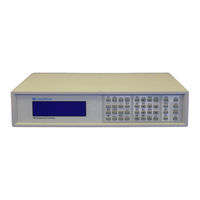
Lakeshore 340 User Manual (178 pages)
Brand:
Lakeshore
| Category:
Temperature Controller
| Size: 1.61 MB
Table of Contents
Declaration of Conformity
3
Table of Contents
5
Introduction
13
General
13
Model 340 Front Panel
13
Temperature Control System
14
Temperature Control System with the Model 340
14
Cooling Source
14
Typical Temperature Control System with Model 340
14
Feedback
15
Control Equation
15
Heating
15
Model 340 Features
15
Configurable Inputs
15
Input Isolation
16
Input Reading Capability
16
Model 340 Temperature Controller Block Diagram
16
Temperature Response Curves and Calcurves
17
Softcal
17
Configurable Heater Output
17
Heater Output Protection
17
Second Control Loop
17
Autotune
17
Setpoint Ramping and Zones
17
Internal Programming
18
Math
18
Alarms, Analog Outputs, and Digital I/O
18
Memory Card
18
Computer Interface
18
Comparison of Control Loops 1 and 2
18
Model 340 Sensor Performance Chart
22
Cooling System Design
23
General
23
Temperature Sensor Selection
23
Temperature Range
23
Sensor Sensitivity
23
Environmental Conditions
24
Measurement Accuracy
24
Sensor Package
24
Calibrated Sensors
24
Traditional Calibration
24
Softcal
25
Silicon Diode Sensor Calibrations and Calcurve
25
Standard Curves
26
Calcurve
26
Sensor Installation
26
Mounting Materials
26
Sensor Location
26
Thermal Conductivity
27
Contact Area
27
Contact Pressure
27
Typical Sensor Installation in a Mechanical Refrigerator
27
Lead Wire
28
Lead Soldering
28
Heat Sinking Leads
28
Thermal Radiation
28
Heater Selection and Installation
28
Heater Resistance and Power
28
Heater Location
29
Heater Types
29
Heater Wiring
29
Considerations for Good Control
29
Thermal Conductivity
29
Thermal Lag
30
Two-Sensor Approach
30
Thermal Mass
30
System Nonlinearity
30
Pid Control
31
Proportional (P)
31
Integral (I)
31
Derivative (D)
31
Examples of PID Control
32
Manual Heater Output
33
Manual Tuning
33
Setting Heater Range
33
Tuning Proportional
33
Tuning Integral
34
Tuning Derivative
34
Autotuning
35
Zone Tuning
36
General
37
Receiving the Model 340
37
Inspection and Unpacking
37
Repackaging for Shipment
37
Safety Summary
38
Safety Symbols
38
Handling Liquid Helium and Liquid Nitrogen
39
Typical Cryogenic Storage Dewar
39
Comparison of Liquid Helium to Liquid Nitrogen
39
Rear Panel Definition
40
Model 340 Rear Panel
40
Line Input Assembly
41
Line Voltage and Fuse Verification
41
Line Voltage Selection
41
AC Line Input Definitions
41
Fuse Replacement
42
Power Cord
42
Power Switch
42
Standard Sensor Inputs
42
Sensor Input Connector and Pinout
42
Power Fuse Access
42
Sensor INPUT a and B Connector Definitions
42
Sensor Lead Cable
43
Grounding and Shielding Sensor Leads
43
Sensor Polarity
43
Four-Lead Sensor Measurement
43
Two-Lead Sensor Measurement
44
Lowering Measurement Noise
44
Heater Output Setup
44
Loop 1 Output
44
Heater Output Connector for Loop 1
44
Heater Output Wiring for Loop 1
45
Heater Protection and Fuse for Loop 1
45
Loop 1 Heater Noise
45
Model 3003 Heater Output Conditioner
45
Loop 2 Output
46
Loop 2 Output Resistance
46
Loop 2 Output Connector
46
Loop 2 Heater Protection
46
Model 3003 Heater Output Conditioner
46
Boosting the Output Power
47
Analog Outputs
47
ANALOG out 1 and 2 BNC Rear Panel Connector Details
47
Digital I/O
48
Relays
48
Front Panel Operation
49
General
49
Turning Power on
49
Display Formats
49
Model 340 Front Panel
49
Normal Display
50
Setting Displays
50
Data Entry Displays
50
Error Displays
50
Keypad Description
50
Keypad Navigation
51
Direct Settings
51
Using Setting Screens
52
Data Entry Screens
52
The Help Key
52
Keypad Time-Out
52
Key Definitions
53
Changing Display Format
54
Number of Readings Displayed
54
Sensor Input
54
Reading Source and Display Units
55
Control Loop Display
55
Large Heater Display
55
Heater Output Display Units
56
Display Contrast
56
Display Backlight On/Off
56
Locking the Keypad
56
Default Values
56
Sensor Input and Temperature Measurement Operation
57
General
57
Sensor Input Setup
57
Sensor Type
57
Sensor Types Recognized by the Model 340
57
Voltage Excitation (Current Autorange)
58
Thermal EMF Compensation with Voltage Excitation
58
Special Sensor Type Configuration
58
Turning an Input off
59
Selecting a Temperature Response Curve
59
Special Sensor Type Configuration
59
Filter and Math
60
Filter
60
Standard Curve Table
60
Max/Min
61
Data Flow
61
Linear Equation
62
Scanner Support
62
Scan Modes
62
Linear Equation Configuration
62
Input Setup with a Scan Mode Active
63
Manual Scanning
63
Auto Scanning
64
Slave Scanning
64
Temperature Control Operation
65
General
65
Control Loops
65
Control Loops on the Normal Display
65
Loop Indication on the Normal Display
65
Loop Indication on Setting Screens
65
Control Output Display
66
Control Loop Enable
66
Control Loop Filter
66
Control Channel
67
Control Modes
67
Control Mode Description
67
Manual Setting of Pid Control Parameters
68
Proportional (P)
68
Integral (I)
68
Derivative (D)
68
Manual Output
68
Selecting an Autotune Control Mode
68
Zone Control Data Entry
69
Record of Zone Settings
70
Using Open Loop Control
71
Setting a Setpoint and Setpoint Units
71
Setpoint Ramping
72
Control Output
72
Heater Output Parameter Settings and Heater Range
72
Full Scale Heater Power at Typical Resistance
73
Analog Output as Loop 2 Control Output
74
Control Output Limits
75
Setpoint Limit
75
Control Output Slope Limit
75
Heater Range Limit
75
Analog Output, Digital I/O. Alarms, and Relay Operation
77
General
77
Analog Outputs
77
Input Mode for Analog Output
78
Example of Low and High Parameter Setting
78
Loop 2 Mode for Analog Output 2
78
Manual Mode Operation of the Analog Outputs
79
Digital Inputs and Outputs (I/O)
79
Digital Output Modes
79
Digital Outputs in Alarm Mode
79
Digital Outputs in Scanner Mode
79
Digital Outputs in Manual Mode
80
Digital Input Modes
80
Input Alarms
80
Enabling an Input Alarm
80
Selecting an Input Alarm Source
81
Input Alarm High and Low Settings
81
Input Alarm Latching
81
Input Alarm Relay Setup
81
Input Alarm Reset
82
Audible Beeper
82
High and Low Relays
82
Selecting a Relay Mode
82
Manually Setting a Relay
82
Instrument Programming
83
General
83
Curve Entry from the Front Panel
83
Curve Numbers and Storage
83
Front Panel Curve Entry Operations
83
Front Panel Curve Edit
84
Recommended Curve Parameters
84
Front Panel Curve Copy
85
Front Panel Curve Erase
85
Softcal
86
Softcal and Silicon Diode Sensors
86
Softcal Temperature Ranges for Silicon Diode Sensors
86
Softcal Accuracy with Silicon Diode Sensors
87
Softcal and Platinum Sensors
87
Softcal Accuracy with Platinum Sensors
87
Softcal Temperature Ranges for Platinum Sensors
87
Creating a Softcal Calibration Curve
88
Internal Programming
88
Program Instructions
88
Internal Programming Operations
92
Enter or Edit an Internal Program
92
Saving a Program
93
Summary of Key Operation
93
Example of an Internal Program (Example 1)
93
Example of Using Subprograms (Example 2)
94
Run an Internal Program
94
Stop a Running Program
94
Sample Program #1
94
Clear Internal Program Memory
95
Data Card Operation
95
Data Logging to a Data Card
95
Storage Capability for a 1 MB Data Card
95
Reading from a Data Card
98
Writing to a Data Card
98
Erasing a Data Card
98
Remote Operation
99
General
99
Ieee-488 Interface
99
IEEE-488 Interface Settings
99
IEEE-488 Command Structure
99
Status Registers
101
IEEE Interface Example Programs
102
IEEE-488 Interface Board Installation for Visual Basic Program
102
GPIB Setting Configuration
103
DEV 12 Device Template Configuration
103
Visual Basic IEEE-488 Interface Program Setup
104
IEEE-488 Interface Program Control Properties
105
Visual Basic IEEE-488 Interface Program
106
IEEE-488 Interface Board Installation for Quick Basic Program
107
Quick Basic Program
107
Typical National Instruments GPIB Configuration from IBCONF.EXE
108
Quick Basic IEEE-488 Interface Program
109
Program Operation
110
Troubleshooting
110
Serial Interface Overview
111
Changing Baud Rate
111
Physical Connection
111
Serial Interface Connections
111
Hardware Support
112
Character Format
112
Message Strings
112
Serial Interface Specifications
112
Message Flow Control
113
Serial Interface Example Programs
113
Visual Basic Serial Interface Program Setup
114
Serial Interface Program Control Properties
115
Visual Basic Serial Interface Program
116
Quick Basic Serial Interface Program Setup
117
Program Operation
118
Troubleshooting
118
Ieee-488/Serial Interface Commands
119
Options and Accessories
141
General
141
Options
141
Accessories
141
Model 2001 RJ-11 Cable Assembly
143
Model 2003 RJ-11 to DE-9 Adapter
143
Optional Model 2002 RJ-11 to DB-25 Adapter
144
Model 3012 Rack-Mount Kit
144
Model Dual Standard 3462 Input Option Card
145
Field Installation
145
Cover and Option Plate Screws
145
Model 340 Mounting Holes and Analog Option Plug
146
Operation
147
Specifications
147
Model 3464 Dual Thermocouple Input Option Card
147
General
147
Model 340 Rear Panel with Model 3462 Option Card Installed
147
Option Installation
148
Sensor Installation
148
Sensor Input Terminals
148
Thermocouple Polarity
148
Measurement Point Connection
149
Grounding and Shielding
149
Operation
149
Default Settings
149
Input Selection
149
Displaying Option Readings
149
Curve Selection
150
Curve Data Format
150
Range Selection
150
Room Temperature Compensation
150
Model 340 Rear Panel with Model 3464 Option Card Installed
148
Standard Thermocouple Curves
150
Computer Interface Commands
151
Thermocouple Temperature Curves
152
Specifications
152
Model 3465 Single Capacitance Input Option Card
152
Option Installation
152
Sensor Installation
152
Sensor Input Connector
152
Measurement Point Connection
152
Grounding and Shielding
152
Operation
153
Input Selection
153
Displaying Option Readings
153
Curve Selection
153
Range Selection
153
Temperature Coefficient
153
Control Channel Changes
153
Computer Interface Commands
153
Specifications
153
Model 3468 Eight-Channel Input Option Card
154
General
154
Option Installation
154
Sensor Installation
154
Sensor Input Connector
154
Sensor Input Cabling
154
Reading Rate
154
Operation
155
General Operation
155
Input Setup
155
Temperature Control
155
Computer Interface Commands
156
Specifications
156
Service
159
General
159
General Maintenance Precautions
159
Electrostatic Discharge
159
General Maintenance
160
Rear Panel Connector Definitions
160
SERIAL I/O RJ-11 Rear Panel Connector Details
160
DIGITAL I/O DA-15 Rear Panel Connector Details
161
RELAYS lo and HI Rear Panel Connector Details
161
ANALOG out 1 and 2 BNC Rear Panel Connector Details
162
SENSOR INPUT a and B Rear Panel Connector Details
162
HEATER OUTPUT Rear Panel Connector Details
162
IEEE-488 Interface Connector
163
IEEE-488 Rear Panel Connector Details
163
Serial Interface Cable and Adapters
164
Model 2001 RJ-11 Cable Assembly Wiring
164
Model 2003 RJ-11 to DE-9 Adapter Wiring Details
164
Top of Enclosure Remove and Replace Procedure
165
Eprom and Novram Replacement
165
Error Messages
166
Location of Internal Components
166
Firmware IC Replacement
167
Updating the Master Firmware from a Data Card
169
A1.0 General
171
Appendix A -Curve Tables
171
Lakeshore 340 Installation Instructions (2 pages)
Input Option Card
Brand:
Lakeshore
| Category:
Measuring Instruments
| Size: 0.14 MB
Related Products
Lakeshore 325
Lakeshore 332
Lakeshore 331E
Lakeshore 331S
Lakeshore 330
Lakeshore 336
Lakeshore 335
Lakeshore 3f Wye
Lakeshore 3f Delta
Lakeshore 3f Polyphase
Lakeshore Categories
Temperature Controller
Indoor Furnishing
Measuring Instruments
Power Supply
Controller
More Lakeshore Manuals