beautypg.com
Manuals
Brands
Lenze Manuals
Inverter
I51AE175B
Lenze I51AE175B Manuals
Manuals and User Guides for Lenze I51AE175B. We have
2
Lenze I51AE175B manuals available for free PDF download: Commissioning, Mounting And Switch-On Instructions
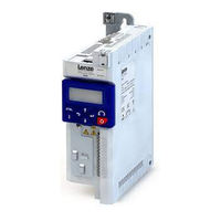
Lenze I51AE175B Commissioning (487 pages)
Inverter Cabinet
Brand:
Lenze
| Category:
Inverter
| Size: 6.49 MB
Table of Contents
Table of Contents
3
1 General Information
11
Read First, then Start
11
2 Safety Instructions
12
Basic Safety Measures
12
Residual Hazards
13
Application as Directed
13
3 Mechanical Installation
14
Dimensions
14
4 Electrical Installation
17
Important Notes
17
Mains Connection
18
1-Phase Mains Connection 230/240 V
18
Connection Plan
18
Fusing and Terminal Data
20
3-Phase Mains Connection 230/240
23
Connection Plan
23
Fusing and Terminal Data
24
3-Phase Mains Connection 400 V
26
Connection Plan
26
Fusing and Terminal Data
27
3-Phase Mains Connection
27
Connection Plan
30
Fusing and Terminal Data
31
Control Connections
33
Networks
33
Canopen/Modbus RTU
33
5 Commissioning
34
Important Notes
34
Operating Interfaces
35
Keypad
35
Engineering Tool "EASY Starter
36
Generate a Connection between Inverter and "EASY Starter
37
Parameter Setting
39
General Notes on Parameters
40
Basic Inverter Settings
41
Basic Motor Settings
44
Function Assignment of the Inputs and Outputs
45
Keypad Parameter List
48
Save Parameter Settings in the Memory Module
66
Save Parameter Settings with Keypad
66
Save Parameter Settings with "EASY Starter
66
6 Diagnostics and Fault Elimination
67
LED Status Display
67
Diagnostics Parameter
68
Logbook
69
Error History Buffer
70
Inverter Diagnostics
73
Network Diagnostics
77
Canopen Diagnostics
78
Modbus Diagnostics
80
Diagnostics of the Inputs and Outputs
81
Digital Inputs and Outputs
81
Analog Inputs and Outputs
82
Wireless-LAN Diagnostics
83
Setpoint Diagnostic
84
Process Controller Status
85
Sequencer Diagnostics
85
Device Identification
86
Device Overload Monitoring (I*T)
88
Heatsink Temperature Monitoring
88
Life-Diagnosis
89
Error Handling
90
Error Types
90
Error Configuration
91
Error Reset
91
Keypad Error Messages
91
Data Handling
92
7 Basic Setting
94
Mains Voltage
95
Control Source Selection
97
Selection of Setpoint Source
98
Keypad Setpoint Default Setting
101
Starting/Stopping Performance
103
Starting Performance
103
Stopping Performance
105
Frequency Limits and Ramp Times
106
Quick Stop
109
S-Shaped Ramps
111
Optical Device Identification
112
8 Motor Control
113
Motor Data
114
Manual Setting of the Motor Data
114
Motor Control Selection
115
V/F Characteristic Control (VFC)
116
Linear V/F Characteristic
117
Square-Law V/F Characteristic
118
User-Definable V/F Characteristic
119
V/F Characteristic Control - Energy-Saving (VFC Eco)
120
Sensorless Vector Control (SLVC)
122
Sensorless Control for Synchronous Motors (SL-PSM)
125
Stall Monitoring
128
Optimisation of Motor Control
129
V/F Voltage Boost
130
Skip Frequencies
131
Optimising the Stalling Behaviour
133
Slip Compensation
135
Oscillation Damping
137
Pole Position Identification Without Movement
138
Optimisation of the Control Loops
140
Options for Optimized Motor Tuning
143
Motor Selection from Motor Catalogue
144
Tuning of the Motor and the Speed Controller
145
Automatic Motor Identification (Energized)
146
Automatic Motor Calibration (Non-Energized)
147
Inverter Characteristics
147
Motor Equivalent Circuit Diagram Data
148
Motor Controller Settings
149
Current Controller
149
Field Controller
150
Field Weakening Controller
150
Field Weakening Controller (Advanced)
150
Imax Controller
151
Flying Restart Controller
152
SLVC Controller
152
Torque Control W/ Freq. Limit
153
Speed Controller
158
Motor Rotating Direction
159
Switching Frequency Changeover
160
Motor Protection
161
Motor Overload Monitoring (I²*T)
162
Current Limits
166
Overcurrent Monitoring
168
Motor Phase Failure Detection
169
Motor Speed Monitoring
170
Motor Torque Monitoring
170
9 Configuring the Network
172
General Network Settings
173
Predefined Process Data Words
191
Device Profile Cia
192
AC Drive Profile
193
Lenze LECOM Profile
194
Further Process Data
196
Parameter Access Monitoring (PAM)
202
Process Data Handling in Case of Error
203
Acyclic Data Exchange
203
Canopen
204
Introduction
204
Node Address Setting
205
Baud Rate Setting
205
Configure Device as Mini Master
206
Diagnostics
207
Emergency Telegram
208
Heartbeat Protocol
208
Process Data Objects
210
Data Mapping
215
Service Data Objects
218
Error Responses
219
Diagnostic Counter
220
LED Status Displays
221
Restart Communication
222
Short Setup
223
Modbus RTU
226
Introduction
226
Node Address Setting
227
Baud Rate Setting
227
Data Format Setting
228
Time-Out Monitoring
228
Diagnostics
228
Function Codes
231
Data Mapping
233
LED Status Displays
234
Restart Communication
235
Response Time Setting
235
Short Setup
236
10 Configuring the Process Controller
238
Basic Process Controller Settings
239
Process Controller - Idle State and Rinse Function
245
Process Controller Idle State
245
Process Controller Rinse Function
247
11 Additional Functions
248
Device Commands
249
Reset Parameters to Default
249
Saving/Loading the Parameter Settings
250
Device Commands for Parameter Change-Over
252
Delete Logbook
252
Keypad
253
Keypad Language Selection
253
Keypad Setpoint Increment
253
Keypad Scaling of Speed Display
253
Keypad Status Display
253
Keypad - Configuration of R/F and CTRL Buttons
254
Wireless LAN (WLAN)
257
WLAN LED Status Displays
257
WLAN Basic Settings
258
Resetting WLAN Settings to Default Setting
260
WLAN Access Point Mode
261
Establishing a Direct WLAN Connection between Smartphone and Inverter
262
Using the Smartphone as "Smart Keypad
263
Establishing a Direct WLAN Connection between Engineering PC and Inverter
264
WLAN Client Mode
266
DC Braking
268
Example 1: Automatic DC Braking When the Motor Is Started
270
Example 2: Automatic DC Braking When the Motor Is Stopped
271
Migration of Lenze Inverter Drives 8200/8400
273
Brake Energy Management
274
Stopping the Deceleration Ramp Function Generator
275
Inverter Motor Brake
276
Load Loss Detection
277
Access Protection
278
Write Access Protection
278
Write Access Protection in the "EASY Starter
280
Write Access Protection in the Keypad
283
Favorites
287
Accessing the "Favorites" with the Keypad
287
Favorites Parameter List (Default Setting)
288
Configuring the "Favorites
289
Parameter Change-Over
292
Example: Selective Control of Several Motors with One Inverter
295
Device Profile Cia 402
297
Holding Brake Control
300
Basic Setting
301
Automatic" Brake Mode (Automatic Operation)
302
Brake Holding Load
304
Brake Closing Level
306
Manual Release of the Holding Brake
308
Flying Restart Circuit
309
Timeout für Fault Reaction
311
Automatic Restart
312
Mains Failure Control
313
Activating the Mains Failure Control
315
Restart Protection
316
Fast Mains Recovery
316
Commissioning the Mains Failure Control
317
UPS Operation
318
Process Data
321
Position Counter
321
Firmware Download
322
Firmware Download with "EASY Starter (Firmware Loader)
322
Additive Voltage Impression
323
Example: Using the Function with a 400-V Inverter
324
12 Sequencer
325
Segment Configuration
327
Sequence Configuration
337
Sequencer Basic Settings
341
13 Flexible I/O Configuration
344
Control Source Change-Over
345
Example 1: Change-Over from Terminal Control to Keypad Control
348
Example 2: Change-Over from Terminal Control to Network Control
349
Start / Stop Motor
350
Example 1: Start/Stop (1 Signal) and Reversal
356
Example 2: Start Forward/Start Reverse/Stop (Edge-Controlled)
357
Example 3: Run Forward/Run Reverse/Stop (Status-Controlled)
359
Example 4: Quick Stop
361
Example 5: Jog Forward/Jog Reverse
362
Example 6: Enable Inverter
364
Setpoint Change-Over
365
Priority of the Setpoint Sources
367
Analog Input Setpoint Source
367
Keypad Setpoint Source
370
Network Setpoint Source
372
Setpoint Source of Preset Setpoints
373
Motor Potentiometer Setpoint Source (MOP)
378
Setpoint Source Segment Setpoints
382
Reset Error
384
Activating DC Braking Manually
386
Releasing Holding Brake Manually
388
Activating Ramp 2 Manually
390
Triggering a User-Defined Fault
392
Functions for Parameter Change-Over
393
Example 1: Activation Via Command (Only When Disabled)
395
Example 2: Activation Via Command (Immediately)
396
Example 3: Activation if the Selection Is Changed (Only if the Inverter Is Disabled)
397
Example 4: Activation if the Selection Is Changed (Immediately)
398
Process Controller Function Selection
399
Sequencer Control Functions
402
Frequency Threshold for "Frequency Threshold Exceeded" Trigger
407
Configuration of Digital Inputs
408
Configuration of Analog Inputs
409
Analog Input 1
409
Example 1: Input Range 0
411
Example 2: Input Range 0
411
13.14.1.3 Example 3: Error Detection
412
Analog Input 1
412
Configuration of Digital Outputs
415
Relay
415
Digital Output 1
418
Networdout1 Status Word
419
Configuration of Analog Outputs
422
Analog Output 1
422
Example 1: Output Voltage 0
424
Example 2: Output Voltage 2
424
14 Technical Data
425
Standards and Operating Conditions
425
Protection of Persons and Device Protection
425
EMC Data
425
Motor Connection
425
Environmental Conditions
426
Electrical Supply Conditions
426
1-Phase Mains Connection 230/240
427
Rated Data
427
3-Phase Mains Connection 230/240
428
Rated Data
428
3-Phase Mains Connection
428
3-Phase Mains Connection 480 V
429
Rated Data
429
15 Appendix
430
Operate and Parameterise the Inverter with Keypad
430
Keypad Operating Mode
431
Keypad Status Display
431
Function of Keypad Keys in Operating Mode
432
Error Reset with Keypad
433
Keypad Parameterisation Mode
434
Parameter Groups
434
Function of the Keypad Keys in the Parameterisation Mode
435
Save Parameter Settings with Keypad
436
Display of Status Words on Keypad
437
Error Codes
438
Parameter Attribute List
454
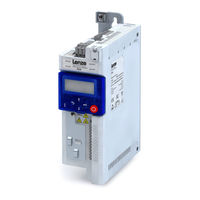
Lenze I51AE175B Mounting And Switch-On Instructions (67 pages)
Brand:
Lenze
| Category:
DC Drives
| Size: 7.26 MB
Table of Contents
Table of Contents
3
About this Document
6
Further Documents
6
Notations and Conventions
7
Safety Instructions
8
Basic Safety Instructions
8
Application as Directed
9
Foreseeable Misuse
9
Residual Hazards
10
Product Information
12
Features
12
Identification of the Products
15
Mechanical Installation
16
Important Notes
16
Preparation
17
Dimensions
18
Electrical Installation
29
Important Notes
29
EMC-Compliant Installation
30
Connection According to UL
31
Important Notes
31
Fusing Data
32
Branch Circuit Protection (BCP)
32
Mains Connection
34
1-Phase Mains Connection 230/240 V
34
Connection Diagrams
34
Terminal Data
36
Fusing Data
37
3-Phase Mains Connection 230/240 V
38
Connection Diagrams
38
Terminal Data
40
Fusing Data
41
3-Phase Mains Connection 230/240 V "Light Duty
41
Connection Diagrams
41
Terminal Data
41
3-Phase Mains Connection 400 V
42
Connection Diagrams
42
Terminal Data
43
Fusing Data
44
3-Phase Mains Connection 400 V "Light Duty
44
Connection Diagrams
44
Terminal Data
44
3-Phase Mains Connection 480 V
45
Connection Diagrams
45
Terminal Data
46
Fusing Data
47
3-Phase Mains Connection 480 V "Light Duty
47
Connection Diagrams
47
Terminal Data
47
Connection to the IT System
48
Control Connections
49
Networks
50
Canopen/Modbus
50
Bacnet
51
Commissioning
52
Important Notes
52
Initial Switch-On and Functional Test
53
Technical Data
54
Standards and Operating Conditions
54
Conformities and Approvals
54
Protection of Persons and Device Protection
54
EMC Data
54
Motor Connection
55
Environmental Conditions
55
Electrical Supply Conditions
55
1-Phase Mains Connection 230/240 V
56
Rated Data
56
3-Phase Mains Connection 230/240 V
58
Rated Data
58
3-Phase Mains Connection 230/240 V "Light Duty
59
Rated Data
59
3-Phase Mains Connection 400 V
60
Rated Data
60
3-Phase Mains Connection 400 V "Light Duty
62
Rated Data
62
3-Phase Mains Connection 480 V Rated Data
63
3-Phase Mains Connection 480 V "Light Duty" Rated Data
65
Environmental Notes and Recycling
66
Related Products
Lenze I51AE175D
Lenze I51AE175F
Lenze I51AE125B
Lenze I51AE137B
Lenze I51AE125D
Lenze I51AE137D
Lenze I51AE137F
Lenze I51AE155B
Lenze I51AE125
Lenze I51AE155
Lenze Categories
DC Drives
Control Unit
Inverter
Engine
Controller
More Lenze Manuals