beautypg.com
Manuals
Brands
Lenze Manuals
Inverter
i55AE330F
Lenze i55AE330F Manuals
Manuals and User Guides for Lenze i55AE330F. We have
2
Lenze i55AE330F manuals available for free PDF download: Manual, Operating Instructions Manual
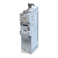
Lenze i55AE330F Manual (702 pages)
Cabinet 0.25 ... 90 kW
Brand:
Lenze
| Category:
Inverter
| Size: 11.83 MB
Table of Contents
Digital Output
2
Table of Contents
3
1 General Information
15
Read First, then Start
15
2 Safety Instructions
16
Basic Safety Measures
16
Residual Hazards
17
Application as Directed
17
3 Mechanical Installation
18
Dimensions
18
4 Electrical Installation
28
Important Notes
28
Mains Connection
29
1-Phase Mains Connection
29
Connection Plan
29
Fusing and Terminal Data
30
1-Phase Mains Connection 230/240 V
32
Connection Plan
32
Fusing and Terminal Data
34
3-Phase Mains Connection 230/240
37
Connection Plan
37
Fusing and Terminal Data
39
3-Phase Mains Connection 400 V
41
Connection Plan
41
Fusing and Terminal Data
42
3-Phase Mains Connection
42
3-Phase Mains Connection 400 V "Light Duty
47
Connection Plan
47
Fusing and Terminal Data
48
Connection Plan
52
Fusing and Terminal Data
53
3-Phase Mains Connection 480 V "Light Duty
58
Connection Plan
58
Fusing and Terminal Data
59
Control Connections
63
Networks
64
Canopen
64
Modbus RTU
65
Modbus TCP
66
Profibus
67
Ethercat
68
Ethernet/Ip
68
Profinet
69
Powerlink
70
Connection of the Safety Module
70
5 Commissioning
71
Important Notes
71
Operating Interfaces
72
Keypad
72
Engineering Tool »EASY Starter
73
Generate a Connection between Inverter and »EASY Starter
74
Parameter Setting
76
General Notes on Parameters
77
Basic Inverter Settings
78
Basic Motor Settings
81
Function Assignment of the Inputs and Outputs
82
Keypad Parameter List
85
Save Parameter Settings in the Memory Module
107
Save Parameter Settings with Keypad
107
Save Parameter Settings with »EASY Starter
107
6 Diagnostics and Fault Elimination
108
LED Status Display
108
Diagnostics Parameter
109
Logbook
110
Error History Buffer
111
Inverter Diagnostics
114
Network Diagnostics
118
Canopen Diagnostics
119
Modbus Diagnostics
122
PROFIBUS Diagnostics
122
Ethernet/Ip Diagnostics
125
PROFINET Diagnostics
126
Ethercat Diagnostics
127
POWERLINK Diagnostics
128
Diagnostics of the Inputs and Outputs
129
Digital Inputs and Outputs
129
Analog Inputs and Outputs
130
Wireless-LAN Diagnostics
132
Setpoint Diagnostic
133
Process Controller Status
133
Sequencer Diagnostics
134
Device Identification
135
Device Overload Monitoring (I*T)
136
Heatsink Temperature Monitoring
137
Life-Diagnosis
137
Error Handling
139
Error Types
139
Error Configuration
140
Error Reset
140
Keypad Error Messages
140
Data Handling
141
7 Basic Setting
143
Mains Voltage
144
Inverter Load Characteristic
146
Control Source Selection
147
Selection of Setpoint Source
148
Keypad Setpoint Default Setting
151
Starting/Stopping Performance
153
Starting Performance
153
Stopping Performance
155
Frequency Limits and Ramp Times
156
Quick Stop
159
S-Shaped Ramps
161
Optical Device Identification
162
8 Motor Control
163
Motor Data
164
Manual Setting of the Motor Data
164
Motor Control Selection
165
V/F Characteristic Control (VFC)
166
Linear V/F Characteristic
167
Square-Law V/F Characteristic
168
User-Definable V/F Characteristic
169
V/F Characteristic Control - Energy-Saving (VFC Eco)
170
V/F Characteristic Control (VFC Closed Loop)
172
Sensorless Vector Control (SLVC)
173
Servo Control for Asynchronous Motors (SC-ASM)
176
Sensorless Control for Synchronous Motors (SL-PSM)
178
Stall Monitoring
181
Optimisation of Motor Control
182
V/F Voltage Boost
183
Skip Frequencies
184
Optimising the Stalling Behaviour
186
Slip Compensation
188
Oscillation Damping
190
Pole Position Identification Without Movement
191
Optimisation of the Control Loops
193
Options for Optimized Motor Tuning
196
Motor Selection from Motor Catalogue
197
Tuning of the Motor and the Speed Controller
198
Automatic Motor Identification (Energized)
199
Automatic Motor Calibration (Non-Energized)
200
Inverter Characteristics
200
Motor Equivalent Circuit Diagram Data
201
Motor Controller Settings
202
Current Controller
202
Field Controller
203
Field Weakening Controller
203
Field Weakening Controller (Advanced)
203
Imax Controller
204
Flying Restart Controller
205
SLVC Controller
205
Torque Control W/ Freq. Limit
206
Slip Controller
210
Speed Controller
211
Motor Rotating Direction
212
Switching Frequency Changeover
213
Motor Protection
214
Motor Overload Monitoring (I²*T)
215
Motor Temperature Monitoring
219
Current Limits
220
Overcurrent Monitoring
222
Motor Phase Failure Detection
223
Motor Speed Monitoring
224
Motor Torque Monitoring
224
9 Configuring the Network
226
General Network Settings
227
Predefined Process Data Words
246
Device Profile Cia 402
247
AC Drive Profile
248
Lenze LECOM Profile
249
Further Process Data
251
Parameter Access Monitoring (PAM)
257
Process Data Handling in Case of Error
258
Acyclic Data Exchange
258
Canopen
259
Introduction
259
Node Address Setting
260
Baud Rate Setting
261
Configure Device as Mini Master
262
Diagnostics
263
Emergency Telegram
264
Heartbeat Protocol
264
Process Data Objects
266
Data Mapping
271
Service Data Objects
274
Error Responses
275
Diagnostic Counter
276
LED Status Displays
277
Restart Communication
278
Short Setup
279
Modbus RTU
282
Introduction
282
Node Address Setting
282
Baud Rate Setting
283
Data Format Setting
283
Time-Out Monitoring
284
Diagnostics
284
Function Codes
287
Data Mapping
289
LED Status Displays
290
Restart Communication
291
Response Time Setting
291
Short Setup
292
Profibus
294
Introduction
294
Communication Time Setting
294
Station Address Setting
295
Baud Rate Setting
296
Monitoring
296
LED Status Displays
298
Diagnostics
298
Functions
299
Data Mapping
300
Parameter Data Transfer
303
Read Parameter Data
305
Write Parameter Data
308
Error Codes for Parameter Data Transfer
311
Restart Communication
312
Short Setup
313
Ethernet/Ip
316
Basic Settings
317
Monitoring
320
LED Status Displays
322
Diagnostics
322
Objects
324
Restart Communication
331
Process Data Transfer
332
Customer Specific Configurations
337
Parameter Data Transfer
342
Short Setup
346
Modbus TCP
348
Introduction
348
Basic Settings
349
Time-Out Behaviour
351
LED Status Displays
352
Diagnostics
353
Function Codes
355
Data Mapping
360
Short Setup
362
Restart Communication
363
Baud Rate Setting
363
Profinet
365
Introduction
365
Basic Settings
366
LED Status Displays
368
Diagnostics
368
Monitoring
370
Data Mapping
371
Parameter Data Transfer
375
Short Setup
377
Ethercat
383
Device Identification
384
Ethercat Configuration
385
LED Status Displays
386
Diagnostics
386
Monitoring
387
Objects
388
Process Data Transfer
389
Parameter Data Transfer
393
Short Setup
394
Powerlink
396
Introduction
396
Basic Settings
397
LED Status Displays
398
Diagnostics
399
Process Data Transfer
399
Monitoring
400
Error Response
400
Supported Objects
400
Short Setup
406
10 Configuring the Process Controller
407
Basic Process Controller Settings
408
Process Controller - Idle State and Rinse Function
414
Process Controller Idle State
414
Process Controller Rinse Function
416
11 Additional Functions
417
Device Commands
418
Reset Parameters to Default
418
Saving/Loading the Parameter Settings
419
Device Commands for Parameter Change-Over
421
Delete Logbook
421
Keypad
422
Keypad Language Selection
422
Keypad Setpoint Increment
422
Keypad Scaling of Speed Display
422
Keypad Status Display
422
Keypad - Configuration of R/F and CTRL Buttons
423
Wireless LAN (WLAN)
426
WLAN LED Status Displays
426
WLAN Basic Settings
427
Resetting WLAN Settings to Default Setting
429
WLAN Access Point Mode
430
Establishing a Direct WLAN Connection between Smartphone and Inverter
431
Using the Smartphone as "Smart Keypad
432
Establishing a Direct WLAN Connection between Engineering PC and Inverter
433
WLAN Client Mode
435
DC Braking
437
Example 1: Automatic DC Braking When the Motor Is Started
439
Example 2: Automatic DC Braking When the Motor Is Stopped
440
Migration of Lenze Inverter Drives 8200/8400
442
Brake Energy Management
443
Use of a Brake Resistor
445
Stopping the Deceleration Ramp Function Generator
447
Inverter Motor Brake
448
Load Loss Detection
449
Access Protection
450
Write Access Protection
450
Write Access Protection in the »EASY Starter
452
Write Access Protection in the Keypad
455
Favorites
459
Accessing the "Favorites" with the Keypad
459
Favorites Parameter List (Default Setting)
460
Configuring the "Favorites
461
Parameter Change-Over
464
Example: Selective Control of Several Motors with One Inverter
467
Device Profile Cia 402
469
Holding Brake Control
472
Basic Setting
473
Automatic" Brake Mode (Automatic Operation)
474
Brake Holding Load
476
Brake Closing Level
478
Manual Release of the Holding Brake
480
Flying Restart Circuit
481
Timeout für Fault Reaction
483
Automatic Restart
484
Mains Failure Control
485
Activating the Mains Failure Control
487
Restart Protection
488
Fast Mains Recovery
488
Commissioning the Mains Failure Control
489
UPS Operation
490
Process Data
493
Position Counter
493
Encoder Settings
495
HTL Encoder
496
Encoder Monitoring
498
Firmware Download
501
Firmware Download with »EASY Starter (Firmware Loader)
501
Additive Voltage Impression
502
Example: Using the Function with a 400-V Inverter
503
12 Sequencer
504
Segment Configuration
506
Sequence Configuration
516
Sequencer Basic Settings
520
13 Safety Functions
523
Safe Torque off (STO)
523
14 Flexible I/O Configuration
525
Control Source Change-Over
526
Example 1: Change-Over from Terminal Control to Keypad Control
529
Example 2: Change-Over from Terminal Control to Network Control
530
Start / Stop Motor
531
Example 1: Start/Stop (1 Signal) and Reversal
537
Example 2: Start Forward/Start Reverse/Stop (Edge-Controlled)
538
Example 3: Run Forward/Run Reverse/Stop (Status-Controlled)
540
Example 4: Quick Stop
542
Example 5: Jog Forward/Jog Reverse
543
Example 6: Enable Inverter
545
Setpoint Change-Over
546
Priority of the Setpoint Sources
548
Analog Input Setpoint Source
548
Keypad Setpoint Source
551
Network Setpoint Source
553
Setpoint Source of Preset Setpoints
554
Motor Potentiometer Setpoint Source (MOP)
559
Setpoint Source Segment Setpoints
563
HTL Input Setpoint Source
565
Example 1: Input Range 10
569
Example 2: Input Range 10
569
Reset Error
570
Activating DC Braking Manually
572
Releasing Holding Brake Manually
574
Activating Ramp 2 Manually
576
Triggering a User-Defined Fault
578
Functions for Parameter Change-Over
579
Example 1: Activation Via Command (Only When Disabled)
581
Example 2: Activation Via Command (Immediately)
582
Example 3: Activation if the Selection Is Changed (Only if the Inverter Is Disabled)
583
Example 4: Activation if the Selection Is Changed (Immediately)
584
Process Controller Function Selection
585
Sequencer Control Functions
588
Frequency Threshold for "Frequency Threshold Exceeded" Trigger
593
Configuration of Digital Inputs
594
Configuration of Analog Inputs
597
Analog Input 1
597
Example 1: Input Range 0
599
Example 2: Input Range 0
599
Example 3: Input Range -10
600
14.14.1.4 Example 4: Error Detection
600
Analog Input 1
600
Configuration of Digital Outputs
603
Relay
603
Digital Output 1
607
Networdout1 Status Word
609
HTL Output
612
Example 1: Pulse Train 0
615
Example 2: Pulse Train 2
616
Configuration of Analog Outputs
617
Analog Output 1
618
Example 1: Output Voltage 0
619
Example 2: Output Voltage 2
619
Analog Output 2
621
15 Technical Data
622
Standards and Operating Conditions
622
Conformities/Approvals
622
Protection of Persons and Device Protection
622
EMC Data
622
Motor Connection
623
Environmental Conditions
623
Electrical Supply Conditions
623
1-Phase Mains Connection
624
Rated Data
624
1-Phase Mains Connection 230/240
625
Rated Data
625
3-Phase Mains Connection 230/240
626
Rated Data
626
3-Phase Mains Connection
627
Rated Data
627
3-Phase Mains Connection 400 V "Light Duty
628
Rated Data
628
3-Phase Mains Connection
629
Rated Data
629
3-Phase Mains Connection 480 V "Light Duty
630
Rated Data
630
16 Appendix
631
Operate and Parameterise the Inverter with Keypad
631
Keypad Operating Mode
632
Keypad Status Display
632
Function of Keypad Keys in Operating Mode
633
Error Reset with Keypad
634
Keypad Parameterisation Mode
635
Parameter Groups
635
Function of the Keypad Keys in the Parameterisation Mode
636
Save Parameter Settings with Keypad
637
Display of Status Words on Keypad
638
Error Codes
639
Parameter Attribute List
659
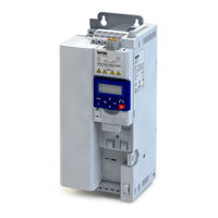
Lenze i55AE330F Operating Instructions Manual (48 pages)
cabinet frequency inverter 0.25-132 kW
Brand:
Lenze
| Category:
Inverter
| Size: 1.44 MB
Table of Contents
General Information
2
Identification of the Products
4
Safety Instructions
6
Technical Data
8
Standards and Operating Conditions
8
Mechanical Installation
9
Important Notes
9
Electrical Installation
12
Brake Resistor Connection
21
Functional Safety
26
Initial Switch-On
28
Troubleshooting
43
Error Codes
44
Led Status
46
Related Products
Lenze i55AE337F
Lenze I55AE330
Lenze i55AE318F
Lenze i55AE322F
Lenze i55AE375F
Lenze i55AE355F
Lenze I55AE315
Lenze I55AE322
Lenze I55AE345
Lenze I55AE355
Lenze Categories
DC Drives
Control Unit
Inverter
Engine
Controller
More Lenze Manuals