beautypg.com
Manuals
Brands
Magtrol Manuals
Measuring Instruments
6510e
Magtrol 6510e Manuals
Manuals and User Guides for Magtrol 6510e. We have
1
Magtrol 6510e manual available for free PDF download: User Manual
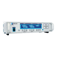
Magtrol 6510e User Manual (76 pages)
Single-Phase Power Analyzer
Brand:
Magtrol
| Category:
Measuring Instruments
| Size: 2.21 MB
Table of Contents
Safety Precautions
3
Revisions to this Manual
4
Revision DATE
4
Table of Revisions
4
Table of Contents
5
Table of FIGURES
8
Preface
9
Purpose of this MANUAL
9
Who Should USE this MANUAL
9
MANUAL Organization
9
Installation/Configuration
9
Conventions USED in this MANUAL
10
Introduction
11
Unpacking Your 6510E Power Analyzer
11
NEW FEATURES of the 6510E Power Analyzer
11
DATA Sheet
12
Controls
15
Front PANEL
15
Front PANEL Controls and Buttons
15
Figure 2-1 Front Panel
15
Enabling Secondary Functions
16
USING Front PANEL Controls and Buttons
16
Figure 2-2 Secondary Function Menu
16
VACUUM Fluorescent DISPLAY (VFD)
18
Contrast SETTINGS
18
Display Guide
19
Figure 2-3 Device Setup Menu
19
Rear Panel
20
REAR PANEL INPUTS and Outputs
20
Figure 2-4 Rear Panel
20
Figure 2-5 Input Module
20
Figure 2-6 RS-232C Interface
21
Figure 2-7 GPIB/IEEE-488 Interface
21
Installation/Configuration
23
Powering up the 6510E
23
LINE Voltage
23
Self-Test
23
Figure 3-1 Program Download Display
23
Figure 3-2 Title Display
23
Main Menu
24
Figure 3-3 Revision Display
24
Figure 3-4 Phase Main Menu
24
Figure 3-5 Custom Main Menu
24
Protecting Your 6510E
25
TRANSIENT Overloads
25
CURRENT Overload
25
SURGE Protection
25
CIRCUIT Breakers
26
Figure 3-6 Transient Voltage Suppression
26
TESTING Instrumentation SETUP
27
WIRING Mode
27
Figure 3-7 Single-Phase, Two-Wire Wiring Schematic
27
Figure 3-8 Single-Phase, Two-Wire Wiring Connection
27
Measurement Filter
28
External Sensor
29
Figure 3-9 Sensor Substituton Wiring Schematic
29
Figure 3-10 Sensor Substitution Wiring Connection
29
Figure 3-11 External Sensor Scale Factor Setup Menu
30
Amp Scaling
31
Figure 3-12 Current/Potential Transformer Connection
31
Figure 3-13 Amp Scaling Setup Menu
31
Figure 3-14 Amp/Volt Scaling Activated
32
Volts SCALING
33
Figure 3-15 Volt Scaling Setup Menu
33
Phase SETUP
34
Figure 3-16 Cycle-By-Cycle Mode
34
SPECIAL Functions
35
Figure 3-17 Hold Mode
35
Figure 3-18 Average Mode
35
Figure 3-19 Peak Hold Clear Display
36
Figure 3-20 Custom Display
36
Operating Principles
37
Analog Processing
37
Volts
37
Amps
38
Operating Principles
38
External Shunt
39
DIGITAL Processing
39
Ac Details
40
DC Details
42
Round-Off Error
44
MEASUREMENT Modes
44
Peak
44
Figure 4-1 Peak Example
44
Peak Hold / Inrush CURRENT
45
Figure 4-2 Peak Hold/Inrush Current Example
45
Rms
46
CREST Factor
46
MEASUREMENT Methods
46
CYCLE-By-CYCLE Mode
46
Continuous Mode
46
Figure 4-3 Crest Factor Example
46
Computer Controlled Operation
47
About the Gpib INTERFACE
47
INSTALLING the Gpib/Ieee-488 Connector Cable
47
Changing the Gpib PRIMARY ADDRESS
47
Figure 5-1 GPIB Installation
47
About the RS-232 INTERFACE
48
Connection
48
Computer Controlled Operation
48
Figure 5-2 GPIB Address Setup Menu
48
Figure 5-3 RS-232 Interface
48
Figure 5-4 Cable Connection Using Null Modem
48
Communication PARAMETERS
49
Baud RATE
49
Checking the 6510E-To-PC Connection
49
Figure 5-5 RS-232 Baud Rate Setup Menu
49
DATA Format
50
Ot Example
50
Oe Example
51
Oa/Ov/Ow/Of Example
51
Programming
51
DATA Termination Characters
51
6510E Communication Commands
52
Configuration Commands
52
DATA Output Commands
54
Calibration
55
Closed-Box Calibration
55
Calibration Schedule
55
Calibration Commands
55
Basic Calibration Process
56
Figure 6-1 Calibration/Verification Test Setup
56
Figure 6-2 Calibration Mode Enabled
56
Optional Features
58
Analog Outputs
58
Specifications
58
Channel ASSIGNMENTS
58
Figure 7-1 Analog Output
58
Hardware Connection
59
Software Configuration
59
Optional Features
59
Figure 7-2 Analog Output Setup Menu
59
Calibration
60
Troubleshooting
62
Appendix A: Schematics
63
MAIN Board - DSP, RAM, Flash
63
MAIN Board - Input/Output, Gpib, RS-232
64
MAIN Board - FPGA
65
INPUT Module - CURRENT
66
INPUT Module - Voltage
67
Key PAD
68
Analog Output
69
Glossary
73
Index
74
Service Information
76
RETURNING Magtrol Equipment for REPAIR And/Or Calibration
76
RETURNING Equipment to Magtrol, INC. (UNITED STATES)
76
RETURNING Equipment to Magtrol SA (Switzerland)
76
Related Products
Magtrol 6530
Magtrol 6200
Magtrol 6400
Magtrol 1 PB 2.7-8
Magtrol 1 PB 2.7-8K
Magtrol 2 PB 2.7-8
Magtrol 2 PB 2.7-8K
Magtrol 2 WB 2.7-8K
Magtrol 3 WB 2.7-8K
Magtrol 4 PB 2.7-8
Magtrol Categories
Measuring Instruments
Controller
Power Supply
Monitor
Transducer
More Magtrol Manuals