beautypg.com
Manuals
Brands
Mitsubishi Electric Manuals
Inverter
FR-A840-06830-GF (280K)
Mitsubishi Electric FR-A840-06830-GF (280K) Manuals
Manuals and User Guides for Mitsubishi Electric FR-A840-06830-GF (280K). We have
3
Mitsubishi Electric FR-A840-06830-GF (280K) manuals available for free PDF download: Instruction Manual
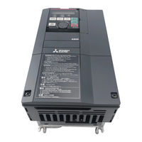
Mitsubishi Electric FR-A840-06830-GF (280K) Instruction Manual (914 pages)
Brand:
Mitsubishi Electric
| Category:
Air Conditioner Accessories
| Size: 23.44 MB
Table of Contents
Table of Contents
2
Safety Instructions
10
Chapter 1 INTRODUCTION
17
Product Checking and Accessories
18
Component Names
20
Operation Steps
22
Related Manuals
24
Chapter 2 INSTALLATION and WIRING
27
Peripheral Devices
28
Inverter and Peripheral Devices
28
Peripheral Devices
30
Removal and Reinstallation of the Operation Panel or the Front Covers
34
Installation of the Inverter and Enclosure Design
38
Inverter Installation Environment
38
Amount of Heat Generated by the Inverter
41
Cooling System Types for Inverter Enclosure
42
Inverter Installation
43
Protruding the Heat Sink through a Panel
45
Terminal Connection Diagrams
47
Main Circuit Terminals
55
Details on the Main Circuit Terminals
55
Main Circuit Terminal Layout and Wiring to Power Supply and Motor
56
Recommended Cables and Wiring Length
58
Earthing (Grounding) Precautions
68
Control Circuit
69
Details on the Control Circuit Terminals
69
Control Logic (Sink/Source) Change
73
Wiring of Control Circuit
75
Wiring Precautions
78
When Using Separate Power Supplies for the Control Circuit and the Main Circuit
78
When Supplying 24 V External Power to the Control Circuit
81
Safety Stop Function
83
Communication Connectors and Terminals
85
PU Connector
85
USB Connector
86
Terminal Block
87
Connection to a Motor with Encoder (Vector Control)
88
Parameter Settings for a Motor with Encoder
95
Connection of Stand-Alone Option Units
98
Connection of the Brake Resistor
98
Connection of the Brake Unit (FR-BU2)
101
Connection of the Brake Unit (FR-BU)
104
Connection of the Brake Unit (BU Type)
104
Connection of the High Power Factor Converter (FR-HC2)
105
Connection of the Multifunction Regeneration Converter (FR-XC)
106
Connection of the Power Regeneration Common Converter (FR-CV)
108
Connection of the Power Regeneration Converter (MT-RC)
109
Connection of the DC Reactor (FR-HEL)
110
Wiring for Use of the CC-Link IE Field Network (FR-A800-GF)
111
System Configuration Example
111
Network Configuration
111
Network Components
111
Component Names of the CC-Link IE Field Network Communication Circuit Board
112
Wiring Method
113
Operation Status Leds
114
Chapter 3 PRECAUTIONS for USE of the INVERTER
117
Electro-Magnetic Interference (EMI) and Leakage Currents
117
Leakage Currents and Countermeasures
117
Techniques and Measures for Electromagnetic Compatibility (EMC)
119
Built-In EMC Filter
121
Power Supply Harmonics
124
Harmonic Suppression Guidelines in Japan
124
Installation of a Reactor
128
Power Shutdown and Magnetic Contactor (MC)
129
Countermeasures against Deterioration of the 400 V Class Motor Insulation
131
Checklist before Starting Operation
132
Failsafe System Which Uses the Inverter
135
Chapter 4 BASIC OPERATION
139
Operation Panel (FR-DU08)
139
Components of the Operation Panel (FR-DU08)
139
Basic Operation of the Operation Panel
141
Digital Characters and Their Corresponding Printed Equivalents
142
Changing the Parameter Setting Value
143
Monitoring the Inverter
144
Monitoring of Output Current and Output Voltage
144
First Priority Monitor Screen
144
Displaying the Set Frequency
144
Easy Setting of the Inverter Operation Mode
145
Frequently-Used Parameters (Simple Mode Parameters)
147
Simple Mode Parameter List
147
Basic Operation Procedure (PU Operation)
150
Setting the Frequency on the Operation Panel (Example: Operating at 30 Hz)
150
Perform PU Operation Using the Setting Dial Like a Potentiometer
151
Setting the Frequency with Switches (Multi-Speed Setting)
152
Setting the Frequency Using an Analog Signal (Voltage Input)
153
Setting the Frequency Using an Analog Signal (Current Input)
154
Basic Operation Procedure (External Operation)
156
Setting the Frequency on the Operation Panel
156
Setting the Frequency and Giving a Start Command with Switches (Multi-Speed Setting) (Pr.4 to Pr.6)
157
Setting the Frequency Using an Analog Signal (Voltage Input)
158
Changing the Frequency (60 Hz, Initial Value) at the Maximum Voltage Input (5 V, Initial Value)
160
Setting the Frequency Using an Analog Signal (Current Input)
161
Changing the Frequency (60 Hz, Initial Value) at the Maximum Current Input (at 20 Ma, Initial Value)
162
Basic Operation Procedure (JOG Operation)
163
Giving a Start Command by Using External Signals for JOG Operation
163
Giving a Start Command from the Operation Panel for JOG Operation
164
Chapter 5 PARAMETERS
166
Parameter List
167
Parameter List (by Parameter Number)
167
Use of a Function Group Number for the Identification of Parameters
202
Parameter List (by Function Group Number)
204
Control Method
217
Vector Control and Real Sensorless Vector Control
219
Changing the Control Method and Mode
222
Selecting the Advanced Magnetic Flux Vector Control
229
Selecting the PM Sensorless Vector Control
231
Low-Speed Range Torque Characteristics
234
Speed Control under Real Sensorless Vector Control, Vector Control, PM Sensorless Vector Control
236
Setting Procedure of Real Sensorless Vector Control (Speed Control)
241
Setting Procedure of Vector Control (Speed Control)
243
Setting Procedure of PM Sensorless Vector Control (Speed Control)
245
Setting the Torque Limit Level
246
Performing High-Accuracy, Fast-Response Control (Gain Adjustment for Real Sensorless Vector Control, Vector Control, and PM Sensorless Vector Control)
255
Troubleshooting in the Speed Control
262
Speed Feed Forward Control, Model Adaptive Speed Control
264
Torque Bias
266
Avoiding Motor Overrunning
270
Notch Filter
272
Torque Control under Real Sensorless Vector Control and Vector Control
273
Torque Control
273
Setting Procedure of Real Sensorless Vector Control (Torque Control)
281
Setting Procedure for Vector Control (Torque Control)
283
Torque Command
284
Speed Limit
288
Torque Control Gain Adjustment
295
Troubleshooting in Torque Control
296
Torque Control by Variable-Current Limiter Control
297
Position Control under Vector Control and PM Sensorless Vector Control
299
About Position Control
299
Setting Procedure of Vector Control (Position Control)
301
Setting Procedure of PM Sensorless Vector Control (Position Control)
303
Simple Positioning Function by Parameters
304
Position Control by the FR-A8AL Pulse Train Input
317
Position Control by Pulse Train Input to the Inverter
320
Clear Signal Selection
321
Pulse Monitor
322
Electronic Gear Settings
326
Position Adjustment Parameter Settings
328
Position Control Gain Adjustment
329
Troubleshooting in Position Control
330
Adjustment During Real Sensorless Vector Control, Vector Control, PM Sensorless Vector Control
333
Speed Detection Filter and Torque Detection Filter
333
Excitation Ratio
333
Gain Adjustment of Current Controllers for the D Axis and the Q Axis
334
E) Environment Setting Parameters
335
Real Time Clock Function
335
Reset Selection / Disconnected PU Detection / PU Stop Selection
337
PU Display Language Selection
340
Buzzer Control
341
PU Contrast Adjustment
341
Display-Off Setting
341
Direct Setting
341
Resetting USB Host Errors
342
Easy Frequency Setting (Volume-Knob-Like Setting) and Key Lock Function Selection
342
Frequency Change Increment Amount Setting
343
Multiple Rating Setting
344
Using the Power Supply Exceeding 480 VAC
346
Parameter Write Selection
346
Password
349
Free Parameter
351
Setting Multiple Parameters by Batch
351
Extended Parameter Display and User Group Function
355
PWM Carrier Frequency and Soft-PWM Control
357
Inverter Parts Life Display
360
Maintenance Timer Alarm
364
Current Average Value Monitor Signal
364
F) Setting of Acceleration/Deceleration Time and Acceleration/Deceleration Pattern
368
Setting the Acceleration and Deceleration Time
368
Acceleration/Deceleration Pattern
373
Remote Setting Function
378
Starting Frequency and Start-Time Hold Function
382
Minimum Motor Speed Frequency and Hold Function at the Motor Start up
383
Shortest Acceleration/Deceleration and Optimum Acceleration/Deceleration (Automatic Acceleration/Deceleration)
385
Lift Operation (Automatic Acceleration/Deceleration)
388
D) Operation Command and Frequency Command
390
Operation Mode Selection
390
Startup of the Inverter in Network Operation Mode at Power-ON
399
Start Command Source and Frequency Command Source During Communication Operation
401
Reverse Rotation Prevention Selection
407
Frequency Setting Using Pulse Train Input
407
JOG Operation
411
Operation by Multi-Speed Setting
412
H) Protective Function Parameter
416
Motor Overheat Protection (Electronic Thermal O/L Relay)
416
Fault Definition
423
Cooling Fan Operation Selection
424
Earth (Ground) Fault Detection at Start
426
Varying the Activation Level of the Undervoltage Protective Function
426
Initiating a Protective Function
426
I/O Phase Loss Protection Selection
427
Retry Function
427
Limiting the Output Frequency (Maximum/Minimum Frequency)
429
Avoiding Machine Resonance Points (Frequency Jump)
430
Stall Prevention Operation
432
Load Characteristics Fault Detection
440
Motor Overspeeding Detection
444
M) Item and Output Signal for Monitoring
445
Speed Indication and Its Setting Change to Rotations Per Minute
445
Monitor Item Selection on Operation Panel or Via Communication
447
Monitor Display Selection for Terminals FM/CA and am
458
Adjustment of Terminal FM/CA and Terminal am
464
Energy Saving Monitoring
468
Output Terminal Function Selection
474
Output Frequency Detection
485
Output Current Detection Function
488
Output Torque Detection Function
489
Remote Output Function
490
Analog Remote Output Function
491
Fault Code Output Selection
493
Pulse Train Output to Announce Cumulative Output Energy
494
Detection of Control Circuit Temperature
495
Encoder Pulse Dividing Output
496
T) Multi-Function Input Terminal Parameters
497
Analog Input Selection
497
Analog Input Terminal (Terminal 1, 4) Function Assignment
501
Analog Input Compensation
502
Response Level of Analog Input and Noise Elimination
504
Frequency Setting Voltage (Current) Bias and Gain
506
Torque (Magnetic Flux) Setting Voltage (Current) Bias and Gain
511
Checking of Current Input on Analog Input Terminal
518
Input Terminal Function Selection
522
Inverter Output Shutoff
525
External Fault Input Signal
526
Selecting the Condition to Activate the Second Function Selection (RT) Signal or the Third Function Selection (X9) Signal
526
C) Motor Constant Parameters
529
Applied Motor
529
Offline Auto Tuning for an Induction Motor
533
Offline Auto Tuning for a PM Motor (under Vector Control)
543
Offline Auto Tuning for a PM Motor (Motor Constant Tuning)
552
Online Auto Tuning
559
Signal Loss Detection of Encoder Signals
562
A) Application Parameters
563
Electronic Bypass Function
564
Self Power Management
570
Brake Sequence Function
573
Start Count Monitor
577
Stop-On-Contact Control
578
Load Torque High-Speed Frequency Control
581
Traverse Function
583
Anti-Sway Control
585
Orientation Control
586
PID Control
602
Changing the Display Increment of Numerical Values Used in PID Control
616
PID Pre-Charge Function
619
Dancer Control
623
Automatic Restart after Instantaneous Power Failure/Flying Start with an Induction Motor
629
Automatic Restart after Instantaneous Power Failure/Flying Start with a PM Motor
636
Offline Auto Tuning for a Frequency Search
639
Power Failure Time Deceleration-To-Stop Function
643
PLC Function
647
Trace Function
650
N) Communication Operation Parameters
660
Wiring and Configuration of PU Connector
660
Wiring and Configuration of RS-485 Terminals
662
Initial Setting of Operation Via Communication
664
Initial Settings and Specifications of RS-485 Communication
671
Mitsubishi Inverter Protocol (Computer Link Communication)
673
MODBUS RTU Communication Specification
687
CC-Link IE Field Network Function Setting (FR-A800-GF)
700
USB Device Communication
702
Automatic Connection with GOT
702
Backup/Restore
703
G) Control Parameters
706
Manual Torque Boost
707
Base Frequency Voltage
708
Load Pattern Selection
709
Excitation Current Low-Speed Scaling Factor
712
Energy Saving Control
713
Adjustable 5 Points V/F
714
SF-PR Slip Amount Adjustment Mode
715
DC Injection Brake, Zero Speed Control, and Servo Lock
716
Output Stop Function
721
Start Signal Operation Selection / Stop Selection
723
Regenerative Brake Selection and DC Feeding Mode
725
Regeneration Avoidance Function
733
Increased Magnetic Excitation Deceleration
736
Slip Compensation
737
Encoder Feedback Control
737
Droop Control
739
Speed Smoothing Control
742
Parameter Clear / All Parameter Clear
744
Copying and Verifying Parameters on the Operation Panel
745
Parameter Copy
745
Parameter Verification
747
Copying and Verifying Parameters Using a USB Memory
748
Checking Parameters Changed from Their Initial Values (Initial Value Change List)
752
CC-Link IE Field Network (FR-A800-GF)
753
Cyclic Transmission
753
I/O Signal List
754
Details of the Remote Input and Output Signals
757
Details of the Remote Register
759
Programming Examples
764
Instructions
771
Troubleshooting
771
Chapter 6 PROTECTIVE FUNCTIONS
773
Inverter Fault and Alarm Indications
773
Reset Method for the Protective Functions
774
Check and Clear of the Fault History
775
List of Fault Displays
777
Causes and Corrective Actions
780
Check First When You Have a Trouble
801
Motor Does Not Start
801
Motor or Machine Is Making Abnormal Acoustic Noise
804
Inverter Generates Abnormal Noise
804
Motor Generates Heat Abnormally
805
Motor Rotates in the Opposite Direction
805
Speed Greatly Differs from the Setting
805
Acceleration/Deceleration Is Not Smooth
806
Speed Varies During Operation
807
Operation Mode Is Not Changed Properly
808
Operation Panel (FR-DU08) Display Is Not Operating
808
The Motor Current Is too Large
808
Speed Does Not Accelerate
809
Unable to Write Parameter Setting
810
Power Lamp Is Not Lit
810
Chapter 7 PRECAUTIONS for MAINTENANCE and INSPECTION
812
Inspection Item
813
Daily Inspection
813
Periodic Inspection
813
Daily and Periodic Inspection
814
Checking the Inverter and Converter Modules
815
Cleaning
816
Replacement of Parts
816
Removal and Reinstallation of the Control Circuit Terminal Block
820
Measurement of Main Circuit Voltages, Currents, and Powers
822
Measurement of Powers
824
Measurement of Voltages
824
Measurement of Currents
824
Measurement of Inverter Input Power Factor
824
Measurement of Converter Output Voltage (between Terminals P and N)
824
Measurement of Inverter Output Frequency
824
Insulation Resistance Test Using Megger
825
Withstand Voltage Test
825
Chapter 8 SPECIFICATIONS
827
Inverter Rating
827
Motor Rating
830
Vector Control Dedicated Motor SF-V5RU (1500 R/Min Series)
830
Vector Control Dedicated Motor SF-THY
833
IPM Motor MM-CF (2000 R/Min Series)
834
Common Specifications
836
Outline Dimension Drawings
838
Inverter Outline Dimension Drawings
838
Dedicated Motor Outline Dimension Drawings
846
Chapter 9 APPENDIX
856
For Customers Replacing the Conventional Model with this Inverter
857
Replacement of the FR-A700 Series
857
Replacement of the FR-A500(L) Series
858
International Standards
859
Acquisition of Type Certification for Ship Classification Standards (400 V Class)
859
Applicable Models
859
Details of Type Certification for Standard Model / Separated Converter Type
859
Details of Type Certification for IP55 Compatible Model
861
Wiring for Compliance with EMC Standards
863
Specification Comparison between PM Sensorless Vector Control and Induction Motor Control
864
Parameters (Functions) and Instruction Codes under Different Control Methods
865
For Customers Using HMS Network Options
894
Ready Bit Status Selection (Pr.349, N240)
898
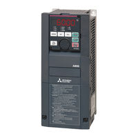
Mitsubishi Electric FR-A840-06830-GF (280K) Instruction Manual (856 pages)
FR-A800 series
Brand:
Mitsubishi Electric
| Category:
Inverter
| Size: 19.77 MB
Table of Contents
Table of Contents
2
Safety Instructions
10
Fire Prevention
11
Chapter 1 INTRODUCTION
17
Product Checking and Accessories
18
Component Names
20
Operation Steps
22
About the Related Manuals
24
Chapter 2 INSTALLATION and WIRING
26
Peripheral Devices
28
Inverter and Peripheral Devices
28
Peripheral Devices
30
Removal and Reinstallation of the Operation Panel or the Front Covers
34
Installation of the Inverter and Enclosure Design
38
Inverter Installation Environment
38
Amount of Heat Generated by the Inverter
41
Cooling System Types for Inverter Enclosure
42
Inverter Installation
43
Protruding the Heat Sink through a Panel
45
Terminal Connection Diagrams
47
Main Circuit Terminals
55
Details on the Main Circuit Terminals
55
Terminal Layout of the Main Circuit Terminals, Wiring of Power Supply and the Motor
56
Applicable Cables and Wiring Length
58
Earthing (Grounding) Precautions
67
Control Circuit
69
Details on the Control Circuit Terminals
69
Control Logic (Sink/Source) Change
73
Wiring of Control Circuit
74
Wiring Precautions
77
When Using Separate Power Supplies for the Control Circuit and the Main Circuit
77
When Supplying 24 V External Power to the Control Circuit
79
Safety Stop Function
81
Communication Connectors and Terminals
84
PU Connector
84
USB Connector
85
Terminal Block
86
Connection to a Motor with Encoder (Vector Control)
87
Wiring Example
91
Parameter Settings for a Motor with Encoder
94
Parameter Settings for the Motor under Vector Control
95
Connection of Stand-Alone Option Units
97
Connection of the Brake Resistor
97
Connection of the Brake Unit (FR-BU2)
101
Connection of the Brake Unit (FR-BU)
102
Connection of the Brake Unit (BU Type)
103
Connection of the High Power Factor Converter (FR-HC2)
104
Connection of the Power Regeneration Common Converter (FR-CV)
104
Connection of the Power Regeneration Converter (MT-RC)
106
Connection of the DC Reactor (FR-HEL)
106
Wiring for Use of the CC-Link IE Field Network (FR-A800-GF)
108
System Configuration Example
108
Network Configuration
108
Network Components
108
Component Names of the CC-Link IE Field Network Communication Circuit Board
109
Wiring Method
110
Operation Status Leds
111
Chapter 3 PRECAUTIONS for USE of the INVERTER
114
Electro-Magnetic Interference (EMI) and Leakage Currents
115
Leakage Currents and Countermeasures
115
Countermeasures against Inverter-Generated EMI
117
Built-In EMC Filter
119
Power Supply Harmonics
122
Harmonic Suppression Guidelines in Japan
122
Installation of a Reactor
126
Power Shutdown and Magnetic Contactor (MC)
127
Countermeasures against Deterioration of the 400 V Class Motor Insulation
129
Checklist before Starting Operation
130
Failsafe System Which Uses the Inverter
133
Chapter 4 BASIC OPERATION
136
Operation Panel (FR-DU08)
137
Components of the Operation Panel (FR-DU08)
137
Basic Operation of the Operation Panel
139
Correspondences between Digital and Actual Characters
140
Changing the Parameter Setting Value
140
Monitoring the Inverter
142
Monitoring of Output Current and Output Voltage
142
First Priority Monitor Screen
142
Displaying the Set Frequency
142
Easy Setting of the Inverter Operation Mode
143
Frequently-Used Parameters (Simple Mode Parameters)
145
Simple Mode Parameter List
145
Basic Operation Procedure (PU Operation)
148
Setting the Frequency on the Operation Panel (Example: Operating at 30 Hz)
148
Perform PU Operation Using the Setting Dial Like a Potentiometer
149
Setting the Frequency with Switches (Multi-Speed Setting)
150
Setting the Frequency Using an Analog Signal (Voltage Input)
151
Setting the Frequency Using an Analog Signal (Current Input)
152
Basic Operation Procedure (External Operation)
154
Setting the Frequency on the Operation Panel
154
Setting the Frequency and Giving a Start Command with Switches (Multi-Speed Setting) (Pr.4 to Pr.6)
155
Setting the Frequency Using an Analog Signal (Voltage Input)
156
Changing the Frequency (60 Hz, Initial Value) at the Maximum Voltage Input (5 V, Initial Value)
157
Setting the Frequency Using an Analog Signal (Current Input)
158
Changing the Frequency (60 Hz, Initial Value) at the Maximum Current Input (at 20 Ma, Initial Value)
159
Basic Operation Procedure (JOG Operation)
160
Giving a Start Command by Using External Signals for JOG Operation
160
Giving a Start Command from the Operation Panel for JOG Operation
161
Chapter 5 PARAMETERS
162
Parameter List
163
Parameter List (by Parameter Number)
163
Use of a Function Group Number for the Identification of Parameters
196
Parameter List (by Function Group Number)
198
Frequency Command
199
Control Method
211
Vector Control and Real Sensorless Vector Control
213
Changing the Control Method and Mode
216
Selecting the Advanced Magnetic Flux Vector Control
223
Selecting the PM Sensorless Vector Control
225
Low-Speed Range Torque Characteristics
228
Speed Control under Real Sensorless Vector Control, Vector Control, PM Sensorless Vector Control
230
5.3 Speed Control under Real Sensorless Vector Control, Vector Control, PM Sensorless Vector Control
231
5.3 Speed Control under Real Sensorless Vector Control, Vector Control, PM Sensorless Vector Control
232
Setting Procedure of Real Sensorless Vector Control (Speed Control)
233
Setting Procedure of Vector Control (Speed Control)
234
Setting Procedure of PM Sensorless Vector Control (Speed Control)
234
Setting the Torque Limit Level
236
Performing High-Accuracy, Fast-Response Control (Gain Adjustment for Real Sensorless Vector Control, Vector Control, and PM Sensorless Vector Control)
245
Troubleshooting in the Speed Control
252
Speed Feed Forward Control, Model Adaptive Speed Control
254
Torque Bias
256
Avoiding Motor Overrunning
260
Notch Filter
262
Torque Control under Real Sensorless Vector Control and Vector Control
264
Torque Control
264
Setting Procedure of Real Sensorless Vector Control (Torque Control)
268
Setting Procedure for Vector Control (Torque Control)
269
Torque Command
271
Speed Limit
275
Torque Control Gain Adjustment
281
Troubleshooting in Torque Control
282
Torque Control by Variable-Current Limiter Control
283
Position Control under Vector Control and PM Sensorless Vector Control
285
About Position Control
285
Operation Example
286
Setting Procedure of Vector Control (Position Control)
287
Setting Procedure of PM Sensorless Vector Control (Position Control)
288
Simple Positioning Function by Parameters
289
Position Control by the FR-A8AL Pulse Train Input
302
To Perform Position Control by Pulse Input to the Inverter
305
Clear Signal Selection
306
Pulse Monitor
307
Electronic Gear Settings
310
Position Adjustment Parameter Settings
312
Position Control Gain Adjustment
313
Troubleshooting in Position Control
314
Adjustment During Real Sensorless Vector Control, Vector Control, PM Sensorless Vector Control
317
Speed Detection Filter and Torque Detection Filter
317
Excitation Ratio
317
Gain Adjustment of Current Controllers for the D Axis and the Q Axis
318
E) Environment Setting Parameters
319
Real Time Clock Function
320
Reset Selection/Disconnected PU Detection/Pu Stop Selection
321
PU Display Language Selection
323
Buzzer Control
323
PU Contrast Adjustment
323
Display-Off Mode
324
Direct Setting
324
Resetting USB Host Errors
325
Setting Dial Potentiometer Mode/Key Lock Operation Selection
325
Frequency Change Increment Amount Setting
326
Multiple Rating Setting
327
Using the Power Supply Exceeding 480 V
328
Parameter Write Selection
329
Password
332
Free Parameter
334
Setting Multiple Parameters as a Batch
334
Extended Parameter Display and User Group Function
338
PWM Carrier Frequency and Soft-PWM Control
340
Inverter Parts Life Display
342
Maintenance Timer Alarm
346
Current Average Value Monitor Signal
347
F) Setting of Acceleration/Deceleration Time and Acceleration/Deceleration Pattern
350
Setting the Acceleration and Deceleration Time
350
Control Block Diagram
352
Acceleration/Deceleration Pattern
355
Remote Setting Function
360
Output Frequency
361
Starting Frequency and Start-Time Hold Function
364
Minimum Motor Speed Frequency and Hold Function at the Motor Start up
365
Shortest Acceleration/Deceleration and Optimum Acceleration/Deceleration (Automatic Acceleration/Deceleration)
366
Lift Operation (Automatic Acceleration/Deceleration)
369
D) Operation Command and Frequency Command
371
Operation Mode Selection
372
Startup in Network Operation Mode at Power-ON
379
Start Command Source and Frequency Command Source During Communication Operation
381
Reverse Rotation Prevention Selection
387
Frequency Setting Via Pulse Train Input
387
JOG Operation
391
Operation by Multi-Speed Setting
392
H) Protective Function Parameter
395
Motor Overheat Protection (Electronic Thermal O/L Relay)
395
Fault Definition
402
Cooling Fan Operation Selection
403
Earth (Ground) Fault Detection at Start
404
Varying the Activation Level of the Undervoltage Protective Function
404
Initiating a Protective Function
405
I/O Phase Loss Protection Selection
405
Retry Function
406
Limiting the Output Frequency (Maximum/Minimum Frequency)
408
Avoiding Machine Resonance Points (Frequency Jump)
409
Stall Prevention Operation
410
Load Characteristics Fault Detection
418
Motor Overspeeding Detection
422
M) Item and Output Signal for Monitoring
423
Speed Indication and Its Setting Change to Rotations Per Minute
423
Monitor Item Selection on Operation Panel or Via Communication
425
Monitor Display Selection for Terminals FM/CA and am
436
Adjustment of Terminal FM/CA and Terminal am
441
Energy Saving Monitoring
445
Output Terminal Function Selection
451
Output Signal List
452
Output Frequency Detection
462
Output Current Detection Function
465
Output Torque Detection Function
466
Remote Output Function
467
Analog Remote Output Function
468
Fault Code Output Selection
470
Pulse Train Output to Announce Cumulative Output Energy
471
Detection of Control Circuit Temperature
472
Encoder Pulse Dividing Output
473
T) Multi-Function Input Terminal Parameters
474
Analog Input Selection
474
Analog Input Terminal (Terminal 1, 4) Function Assignment
478
Analog Input Compensation
479
Response Level of Analog Input and Noise Elimination
481
Frequency Setting Voltage (Current) Bias and Gain
483
Torque (Magnetic Flux) Setting Voltage (Current) Bias and Gain
488
Checking of Current Input on Analog Input Terminal
493
Input Terminal Function Selection
497
Inverter Output Shutoff
500
Selecting the Condition to Activate the Second Function Selection (RT) Signal or the Third Function Selection (X9) Signal
501
Start Signal Operation Selection
503
C) Motor Constant Parameters
506
Applied Motor
506
Offline Auto Tuning
510
Offline Auto Tuning for a PM Motor (Motor Constant Tuning)
520
Online Auto Tuning
528
Signal Loss Detection of Encoder Signals
531
A) Application Parameters
532
Electronic Bypass Function
533
Self Power Management
539
Brake Sequence Function
542
Start Count Monitor
546
Stop-On-Contact Control
547
Load Torque High-Speed Frequency Control
550
Traverse Function
552
Anti-Sway Control
554
Orientation Control
555
Flux Vector Control
561
PID Control
571
Adjustment Procedure
581
Changing the Display Increment of Numerical Values Used in PID Control
585
PID Pre-Charge Function
588
Dancer Control
591
Automatic Restart after Instantaneous Power Failure/Flying Start with an Induction Motor
598
Automatic Restart after Instantaneous Power Failure/Flying Start with an IPM Motor
605
Offline Auto Tuning for a Frequency Search
607
Power Failure Time Deceleration-To-Stop Function
611
PLC Function
615
Trace Function
617
N) Communication Operation Parameters
626
Wiring and Configuration of PU Connector
626
Wiring and Configuration of RS-485 Terminals
628
Initial Setting of Operation Via Communication
631
Initial Settings and Specifications of RS-485 Communication
637
Mitsubishi Inverter Protocol (Computer Link Communication)
638
Setting Items and Set Data
647
MODBUS RTU Communication Specification
653
Communication Specifications
654
Message Format
654
Function Code List
656
CC-Link IE Field Network Function Setting (FRA800-GF)
666
USB Device Communication
667
Automatic Connection with GOT
668
Backup/Restore
669
G) Control Parameters
672
Manual Torque Boost
673
Base Frequency Voltage
674
Load Pattern Selection
675
Excitation Current Low-Speed Scaling Factor
678
Energy Saving Control
679
Adjustable 5 Points V/F
680
SF-PR Slip Amount Adjustment Mode
681
DC Injection Brake, Zero Speed Control, and Servo Lock
682
Output Stop Function
687
Stop Selection
689
Regenerative Brake Selection and DC Feeding Mode
690
Stop Selection
690
Regeneration Avoidance Function
697
Increased Magnetic Excitation Deceleration
700
Slip Compensation
701
Encoder Feedback Control
701
Droop Control
703
Speed Smoothing Control
706
Parameter Clear / All Parameter Clear
708
Copying and Verifying Parameters on the Operation Panel
709
Parameter Copy
709
Parameter Verification
710
Copying and Verifying Parameters Using a USB Memory
712
Checking Parameters Changed from Their Initial Values (Initial Value Change List)
716
CC-Link IE Field Network (FR-A800-GF)
717
Cyclic Transmission
717
I/O Signal List
718
Details of the Remote Input and Output Signals
721
Details of the Remote Register
723
Programming Examples
728
Instructions
734
Troubleshooting
735
Chapter 6 PROTECTIVE FUNCTIONS
736
Inverter Fault and Alarm Indications
737
Protective Functions
737
Reset Method for the Protective Functions
738
Check and Clear of the Faults History
739
List of Fault Displays
741
Causes and Corrective Actions
744
Check First When You Have a Trouble
764
Motor Does Not Start
764
Motor or Machine Is Making Abnormal Acoustic Noise
767
Inverter Generates Abnormal Noise
767
Motor Generates Heat Abnormally
768
Motor Rotates in the Opposite Direction
768
Speed Greatly Differs from the Setting
768
Acceleration/Deceleration Is Not Smooth
769
Speed Varies During Operation
770
Operation Mode Is Not Changed Properly
771
Operation Panel (FR-DU08) Display Is Not Operating
771
The Motor Current Is too Large
771
Speed Does Not Accelerate
772
Unable to Write Parameter Setting
773
Power Lamp Is Not Lit
773
Chapter 7 PRECAUTIONS for MAINTENANCE and INSPECTION
774
Inspection Item
775
Precautions for Maintenance and Inspection
775
Daily Inspection
775
Periodic Inspection
775
Daily and Periodic Inspection
776
Checking the Inverter and Converter Modules
777
Inspection
777
Cleaning
778
Replacement of Parts
778
Inverter Replacement
782
Measurement of Main Circuit Voltages, Currents, and Powers
783
Measurement of Powers
785
Measurement of Voltages and Use of PT
785
Measurement of Currents
785
Use of CT and Transducer
786
Measurement of Inverter Input Power Factor
786
Measurement of Converter Output Voltage (between Terminals P and N)
786
Measurement of Inverter Output Frequency
786
Insulation Resistance Test Using Megger
787
Pressure Test
787
Chapter 8 SPECIFICATIONS
788
Inverter Rating
789
Motor Rating
793
Vector Control Dedicated Motor SF-V5RU (1500 R/Min Series)
793
Motor Rating
795
Vector Control Dedicated Motor SF-THY
796
IPM Motor MM-CF (2000 R/Min Series)
797
Common Specifications
799
Outline Dimension Drawings
801
Inverter Outline Dimension Drawings
801
Dedicated Motor Outline Dimension Drawings
809
Chapter 9 APPENDIX
818
For Customers Replacing the Conventional Model with this Inverter
819
Replacement of the FR-A700 Series
819
Replacement of the FR-A500(L) Series
820
Wiring Instructions
820
Specification Comparison between PM Sensorless Vector Control and Induction Motor Control
822
Parameters (Functions) and Instruction Codes under Different Control Methods
823
For Customers Using HMS Network Options
850
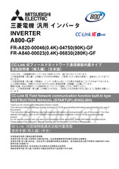
Mitsubishi Electric FR-A840-06830-GF (280K) Instruction Manual (174 pages)
Brand:
Mitsubishi Electric
| Category:
Inverter
| Size: 10.39 MB
Table of Contents
Table of Contents
59
Inverter Installation and Precautions
61
Wiring
62
Basic Operation
67
Failsafe System Which Uses the Inverter
69
Precautions for Use of the Inverter
69
Parameter List
71
Related Products
Mitsubishi Electric FR-A840-06830 (280K)
Mitsubishi Electric FR-A840-06830-R2R
Mitsubishi Electric FR-A840-06830-E-R2R
Mitsubishi Electric FR-A840-06830-GF 280K Series
Mitsubishi Electric FR-A840-06830-GN
Mitsubishi Electric FR-A840-06830 280K
Mitsubishi Electric FR-A840-06100-GF (250K)
Mitsubishi Electric FR-A840-06100-R2R
Mitsubishi Electric FR-A840-06100 250K
Mitsubishi Electric FR-A840-06100-E-R2R
Mitsubishi Electric Categories
Air Conditioner
Controller
Projector
Inverter
Heat Pump
More Mitsubishi Electric Manuals