beautypg.com
Manuals
Brands
Mitsubishi Electric Manuals
Touch terminals
GT16
Mitsubishi Electric GT16 Manuals
Manuals and User Guides for Mitsubishi Electric GT16. We have
2
Mitsubishi Electric GT16 manuals available for free PDF download: User Manual, Connection Manual
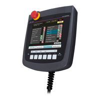
Mitsubishi Electric GT16 User Manual (1306 pages)
GOT1000 Series
Brand:
Mitsubishi Electric
| Category:
Touch terminals
| Size: 45.19 MB
Table of Contents
Introduction
9
Safety Precautions
3
Table of Contents
9
37. Connection to Jtekt Plc
22
Table of Contents
29
Rough Procedure
45
Overall Configuration
47
System Equipment
48
Option
49
General Specifications
55
Performance Specifications
56
Power Supply Specifications
58
Battery Specifications
59
Front Panel
61
Back Panel
62
Opening and Closing of Environmental Protection Back Cover
63
Top Face (Interface)
64
UL, Cul Standards
65
Requirements to Meet EMC Directive
66
EMC Directive-Compliant System Configuration
68
Precautions for Wiring/Connecting the EMC Directive-Compliant Product
70
Applicable CF Card
73
Installing and Removing Procedures of the CF Card
74
Memory Card Adaptor
76
Battery
77
Protective Sheet
78
Emergency Stop Switch Guard Cover
79
Connector Conversion Box
80
Connector Conversion Box (GT16H-CNB-37S)
97
Installing Procedure
103
Hanging on a Wall
104
Installing To/Removing from Panel
105
Overview of Communication Cable
107
Installing and Removing of External Cable
109
Internal Wiring Diagram of GT16 Handy
113
Power Wiring
114
The Cause of Malfunctions Related Wiring/Remedy
115
Wiring Inside and Outside the Panel
117
Attaching Surge Killers to Control Equipment
118
Switch Wiring
119
Switch Wiring Example
120
Operation Switch Wiring
122
LED Setting of Operation Switch
123
Operation Switch Name Sheet Creation
125
Emergency Stop Switch Wiring
126
Grip Switch
128
LED Settings of Grip Switch
129
Utility Execution
131
Utility Function List
132
Utility Function
134
Utility Display
135
Display Operation of Main Menu
137
Main Menu
138
Utility Basic Configuration
139
Basic Operation of Settings Change
140
GOT Main Unit Function Settings
143
Operation of Time Setting
144
Transparent Setting (Transparent Mode Setting)
147
Cleaning of Display Section (Clean)
148
Behavior of Duplicate Ips
150
License Management
153
Display Settings
155
Display Operation of Display Setting
156
Display Setting Operations
157
Brightness, Contrast Adjustment
159
Operation Settings (Settings Regarding Operation)
160
Display Operation of Operation Setting
161
Setting Operation of Operation
162
Security Level Change
163
Utility Call Key Setting
165
Utility Call Key Setting Operation
166
Adjusting the Touch Panel Position (Touch Panel Calibration Setting)
167
USB Mouse/Keyboard Setting
169
Softgot-GOT Link Function Setting
171
VNC(R) Server Function Setting Operation
174
Maintenance Function
176
Addition Times Reset
178
GOT Start Time
180
GOT Information
182
Communication Setting
185
Communication Setting Contents
186
Communication Setting Operation
188
Communication Detail Setting
192
Display Contents of Communication Detail Setting
194
Ethernet Setting
199
Display Contents of Ethernet Setting
200
Monitor Screens
203
Display Operation of Monitor Screens
204
Debug Setting
205
Backup/Restoration Setting
207
Trigger Backup Settings
209
Trigger Backup Setting Operation
210
Memory/Data Control
211
Backup/Restoration
212
GOT Data Package Acquisition
213
Display Example of Got Data Package Acquisition
214
Got Data Package Acquisition Operation
214
Memory Card Format
216
Memory Information
218
USB Device Status Display
219
SRAM Control
221
Motion Program (SV43) I/O
225
Diagnostic Functions
227
System Alarm
228
Memory Check
230
Drawing Check
233
Drawing Check Operation
234
Font Check
237
Touch Panel Check
239
I/O Check
241
Ethernet Status Check
244
Batch Self Check
245
Operation of Batch Self Check
246
Data Storage Location
249
OS Version Confirmation
251
Capacity Confirmation of the Project Data Downloading Location
252
Various Data Control
253
The Display Example of Alarm Information
254
Advanced Recipe Information
261
Example of Advanced Recipe Information Display
263
Logging Information
281
Example of Logging Information Display
282
Operation Log Information
291
Example of Operation Log Information Display
293
Hard Copy Information
306
Special Data Information
312
Special Data Information Display Example
313
Operator Information
318
Function Setting
331
Os/Project Information
334
Display Example of os Information
335
Operation of os Information
336
Project Information
340
Display Example of Project Information
341
Bootos and Standard Monitor os Required for Installation
352
Prior Preparations for Installing Bootos and Standard Monitor os
353
Bootos and Standard Monitor os Installation Using CF Card or USB Memory
354
Installing When Starting the GOT
355
Installing Using the Data Control Function (Utility)
357
When Installing the Different Version of Bootos, Standard Monitor os
359
Coreos
361
When the Coreos Cannot be Installed
364
Setting the Communication Interface
365
Setting Connected Equipment (Channel Setting)
366
I/F Communication Setting
376
Precautions
378
Writing the Communication Settings and Common Settings Onto the GOT
379
Checking the Project Data and os Writing on GOT
380
Maintenance and Inspection
381
Daily Inspection
382
Cleaning Method
383
Battery Voltage Low Detection and Battery Replacement
384
Backlight Shutoff Detection
387
Backlight Shutoff Detection and External Alarm
388
GOT Restoration Sheet
389
Troubleshooting
396
Error Message and System Alarm
399
List of Error Message/System Alarm
401
Appendix.1 External Dimensions
411
Appendix.2 Usage Condition of Utility Function
414
Appendix.3 Transportation Precautions
417
Safety Precautions
429
Introduction
435
Gt16 Handy Got User's Manual 2/2
440
Connectable Model List
440
Connectable Model List
441
CC-Link Module/Peripheral Module
442
System Configuration
444
Precautions
445
Connection Diagram
446
GOT Side Settings
447
PLC Side Setting
448
GOT Side Settings
449
Ethernet Connection
450
RS-422 Cable
452
Device Range that Can be Set
453
Precautions
454
GOT Side Settings
455
Device Range that Can be Set
456
Connecting to Versamax Micro
457
System Configuration for Connecting to SIMATIC S7-300/400 Series
458
Connecting to MODBUS Equipment
459
Device Range that Can be Set
460
Manuals
461
Abbreviations and Generic Terms
462
How to Read this Manual
467
Mitsubishi Plc Connections
469
Direct Connection to CPU
469
Connectable Model List
471
Direct Connection to Cpu
471
Connecting to LCPU
474
Connecting to QCPU
474
System Configuration
474
Connecting to ACPU
475
Connecting to Qnacpu
475
Connecting to MELSEC Iq-F Series
476
Connecting to FXCPU
478
Connecting to the Motion Controller CPU
482
Connecting to WSCPU
482
Cable
483
Connection Diagram
483
Communication Detail Settings
484
GOT Side Settings
484
Setting Communication Interface (Communication Settings)
484
GX Works2 Settings
486
L6ADP-R4 Adapter Settings
486
PLC Side Setting
486
Precautions
487
Computer Link Connection
489
Connectable Model List
489
Plc/Motion Controller CPU
489
Serial Communication Module/Computer Link Module
492
Connecting to MELSEC Iq-R Series
493
System Configuration
493
Connecting to QCPU (Q Mode)
494
Connecting to LCPU
495
Connecting to QCPU (a Mode)
495
Connecting to Qnacpu (Qnacpu Type)
496
Connecting to Qnacpu (Qnascpu Type)
497
Connecting to ACPU (Ancpu Type)
498
Connection Diagram
499
GOT Side Settings
500
PLC Side Setting
502
Connecting Serial Communication Module (Q, L Series)
503
Connecting Serial Communication Module (Qna Series)
504
Connecting Computer Link Module
506
Precautions
509
Connectable Model List
511
Ethernet Module
514
System Configuration
515
Connection to Built-In Ethernet Port CPU or C Controller Module
519
Connecting to Display I/F
521
Connecting to CC-Link IE Field Network Ethernet Adapter Module
522
Connecting to PERIPHERAL I/F
523
GOT Side Settings
524
Ethernet Setting
525
Routing Parameter Setting
526
PLC Side Setting
527
Connecting to Built-In Ethernet Port CPU (One-To One Connection)
528
Connecting to Built-In Ethernet Port CPU (Multiple Connection)
529
Connecting to Ethernet Module (MELSEC Iq-R Series)
531
Connecting to Built-In Ethernet Port CPU (One-To-One Connection)
536
Connecting to Built-In Ethernet Port CPU (Multiple Connection)
538
Connecting to Ethernet Module (Q/L Series)
540
Connecting to C Controller Module (Q Series)
543
Connecting to Ethernet Module (Qna Series)
546
Connecting to Ethernet Module (a Series)
549
Connecting to Ethernet Module (FX Series)
553
Connecting to Display I/F (CNC C70)
559
Connecting to CC-Link IE Field Network Ethernet Adapter Module
561
Connecting to PERIPHERAL I/F (Built-In Ethernet Port Motion Controller CPU)
563
Precautions
566
Connecting AJ65BT-R2N
577
Switch Setting of CC-Link Module (Q Series)
579
Parameter Setting (When Connecting to C Controller Module (Q Series))
580
Mitsubishi Fa Device Connections
583
Connectable Model List
585
Connecting to FREQROL-E500/S500/S500E/F500J/D700/F700PJ
587
Connecting to FREQROL E700/Sensorless Servo (FREQROL-E700EX)
588
Connecting to FREQROL-A700/F700/F700P
589
Connecting to FREQROL-A800/F800
591
Connecting to MD-CX522-[ ][ ]K(-A0)
593
Connection Diagram
594
GOT Side Settings
598
FREQROL Series Inverter Side Settings
600
Connecting FREQROL-F500, F500L Series
601
Connecting FREQROL-V500, V500L Series
602
Connecting FREQROL-D700/F700PJ Series
603
Connecting FREQROL-F700/F700P Series
604
Connecting FREQROL-A700 Series
605
Connecting FREQROL-A800/F800 Series
607
Connecting Sensorless Servo (FREQROL-E700EX Series)
609
Connecting MD-CX522-[ ][ ]K(-A0)
610
Station Number Setting
611
Device Range that Can be Set
612
Inverter Connection
612
Precautions
612
Connectable Model List
613
Servo Amplifier Connection
613
Connecting to the MELSERVO-J2-Super, MELSERVO-J2M Series
614
System Configuration
614
Connecting to the MELSERVO-J4, J3 Series
615
Connecting to the MELSERVO-JE Super Series
617
Cable
618
Connection Diagram
618
Cable
620
Communication Detail Settings
621
GOT Side Settings
621
Setting Communication Interface (Communication Settings)
621
Connecting to the MELSERVO-J2-Super Series
622
Setting on Servo Amplifier Side
622
Connecting to the MELSERVO-J2M Series
623
Connecting to the MELSERVO-J4, J3, JE Series
624
Station Number Setting
624
Device Range that Can be Set
625
Precautions
625
Connectable Model List
627
Connecting to Robot Controller (Crnd-700)
627
Robot Controller Connection
627
System Configuration
627
Communication Detail Settings
628
GOT Side Settings
628
Setting Communication Interface (Communication Settings)
628
Ethernet Setting
629
Connecting to Robot Controller (Crnd-700)
630
PLC Side Setting
630
Device Range that Can be Set
631
Precautions
631
Cnc Connection
633
Connectable Model List
633
Direct Connection to CPU
633
System Configuration
633
Ethernet Connection
634
Cable
635
Connection Diagram
635
Communication Detail Settings
636
GOT Side Settings
636
Setting Communication Interface (Communication Settings)
636
Ethernet Setting
637
CNC Side Settings
638
Ethernet Connection
638
Device Range that Can be Set
640
Direct Connection to CPU
640
Ethernet Connection
640
Precautions
640
Connectable Model List
641
Connecting to an Energy Measuring Unit/Electronic Multi-Measuring Instrument
641
Energy Measuring Unit/Electric Multi-Measuring Instrument Connection
641
System Configuration
641
Cable
642
Connection Diagram
642
Communication Detail Settings
643
GOT Side Settings
643
Connecting to an Energy Measuring Unit/Electronic Multi-Measuring Instrument
644
Setting of Energy Measuring Unit/Electric Multi-Measuring Instrument
644
Station Number Setting
644
Device Range that Can be Set
645
Precautions
646
Multiple Got Connections
647
Connectable Model List
649
Got Multi-Drop Connection
649
System Configuration
650
Cable
651
Connection Diagram
651
Communication Detail Settings
653
GOT Side Settings
653
Setting Communication Interface (Communication Settings)
653
Setting Communication Interface (Communication Settings)
654
Setting of Serial Multi-Drop Connection Unit
654
Write the os
654
Setting of Connection Conversion Adapter
657
Setting Switches
657
Precautions
658
Multi-Channel Function
659
What Is Multi-Channel Function
661
System Configuration
662
General Flow from System Selection to Drawing
663
GOT Side Settings
663
Determining the Connection Type and Channel No. (System Selection)
664
Determining the GOT Side Interface (Interface Selection)
665
Setting for Communication Settings
668
Items to be Checked before Starting Drawing
669
Precautions
671
Precautions for Use
671
Multi-Channel Function Check Sheet
672
Fa Transparent Function
675
Compatible Software
677
FA Transparent Function
677
List of Models that Can be Monitored
682
List of Models that Can be Monitored
683
GX Works3, CW Configurator, GX Works2, GX Developer, GX Logviewer, MX Component, MX Sheet, CPU Module Logging Configuration Tool, Setting/Monitoring Tool for C Controller Module
694
System Configuration
694
PX Developer, GX Configurator
696
MT Developer, MT Works2
697
MR Configurator, MR Configurator2
699
FR Configurator
701
FX Configurator-FP, FX3U-ENET-L Configuration Tool
701
NC Configurator
702
RT Toolbox2
702
GOT Side Settings
703
Setting Communication Interface
703
Accessing by GX Works3
705
Personal Computer Side Setting
705
Accessing by CW Configurator
709
Accessing the PLC by the GX Developer, PX Developer, GX Configurator
711
Accessing by GX Works2
716
Accessing by GX Logviewer
725
Accessing PLC by GX Configurator-QP
726
Accessing by the MT Developer
727
Accessing by MT Works2
728
Accessing the Inverter by the FR Configurator
730
Accessing the Servo Amplifier by the MR Configurator
730
Accessing the Servo Amplifier by the MR Configurator2
730
Accessing by FX3U-ENET-L Configuration Tool
731
Accessing PLC by FX Configurator-FP
731
Accessing by RT Toolbox2
732
Accessing by MELSOFT Navigator
734
Accessing by NC Configurator
734
Accessing by CPU Module Logging Configuration Tool
735
Accessing by Setting/Monitoring Tool for C Controller Module
735
Precautions
737
Precautions Common to each Software
737
When Using GX Works3, GX Works2, GX Developer
739
When Using MT Developer, MT Works2
740
When Using FR Configurator
741
When Using MR Configurator, MR Configurator2
741
Connections to Non-Mitsubishi Products
743
Connectable Model List
745
Connection to Iai Robot Controller
745
System Configuration
746
System Configuration for Connecting to X-SEL, SSEL, ASEL, PSEL
746
System Configuration for Connecting to PCON, ACON, SCON, ERC2
747
Cable
756
Connection Diagram
756
Cable
757
Communication Detail Settings
760
GOT Side Settings
760
Setting Communication Interface (Communication Settings)
760
Connecting to X-SEL
762
Robot Controller Side Setting
762
Connecting to PCON, ACON, SCON
763
Connecting to SSEL, ASEL, PSEL
763
Connecting to ERC2
764
Station NO. Setting
764
Device Range that Can be Set
765
Precautions
765
Connectable Model List
767
Connection to Omron Plc
767
Serial Connection
768
System Configuration for Connecting to CPM1, CPM1A, CPM2A, CPM2C or CQM1
768
System Configuration for Connecting to CQM1H
769
System Configuration for Connecting to CJ1H, CJ1G, CJ1M, CJ2H, or CJ2M
770
System Configuration for Connecting to CP1H, CP1L, or CP1E
771
System Configuration Fro Connecting to C200HS, C200H, C200HX, C200HG, C200HE
772
System Configuration for Connecting to CS1H, CS1G, or CS1D
773
System Configuration for Connecting to C1000H or C2000H
774
System Configuration for Connecting to CV500, CV1000, CV2000, or CVM1
774
Connection Diagram
775
GOT Side Settings
777
PLC Side Setting
778
Connecting to CJ1, CJ2, CS1, CP1H, CP1L, or CP1E
779
Connecting to CV500/CV1000/CV2000 or CVM1
780
Connecting to Connection Cable
781
Connecting to Rack Type Host Link Unit
781
Connecting to Communication Board, Serial Communication Board (CQM1-SCB41)
784
Connecting to Serial Communication Unit
784
Connecting to Serial Communication Board (CS1W-SCB21(-V1), CS1W-SCB41(-V1))
785
Connecting to RS-422A Converter
786
Connecting to RS-422A/485 Option Board
786
Ethernet Connection
787
System Configuration
787
GOT Side Settings
789
PLC Side Setting
791
Device Range that Can be Set
792
Precautions
792
Connectable Model List
793
Connection to Omron Temperature Controller
793
Connecting to the THERMAC NEO Series
794
System Configuration
794
Connecting to the INPANEL NEO
795
Cable
796
Connection Diagram
796
Cable
797
Communication Detail Settings
798
GOT Side Settings
798
Setting Communication Interface (Communication Settings)
798
Connecting E5AN, E5EN, E5CN, E5GN
799
Connecting E5ZN
799
Connection to Interface Converter (K3SC-10)
799
Temperature Controller Side Setting
799
Station NO. Setting
800
Device Range that Can be Set
801
Precautions
801
Connectable Model List
803
Connection to Keyence Plc
803
Serial Connection
804
Connection Diagram
808
GOT Side Settings
810
PLC Side Setting
811
Ethernet Connection
813
GOT Side Settings
814
PLC Side Setting
815
Device Range that Can be Set
816
Connectable Model List
817
Connection to Koyo Ei Plc
817
System Configuration
818
Connecting to Directlogic 05 or Directlogic 06 Series
820
Connecting to D2-240, D2-250-1 or D2-260
822
Connecting to PZ
823
Connection Diagram
824
GOT Side Settings
828
PLC Side Setting
829
Connecting to SU-5M/6M
830
Connecting to U-01DM
831
Connecting to D0-DCM
832
Device Range that Can be Set
833
System Configuration
836
Connecting to PC2J, PC2JS or PC2JR
838
Connecting to PC2JC, PC216P or PC2J16PR
839
Connection Diagram
840
TXU-2051 Setting
844
Link Unit Setting
845
Connecting to JW-21CU or JW-22CU
848
Connecting to JW-31CUH, JW-32CUH or JW-33CUH
849
Connecting to JW-50CUH, JW-70CUH, JW-100CUH or JW-100CU
850
Connecting to Z-512J
850
Cable
851
Connection Diagram
851
Cable
852
Communication Detail Settings
853
GOT Side Settings
853
Setting Communication Interface (Communication Settings)
853
Connecting to JW-22CU, JW-70CUH, JW-100CUH or JW-100CU
854
PLC Side Setting
854
Connecting to JW-32CUH, JW-33CUH or Z-512J
855
Connecting to the Link Unit (JW-21CM)
855
Connecting to the Link Unit (JW-10CM or ZW-10CM)
856
Device Range that Can be Set
857
(Pc-955-[ ]/M,C5, Pc-935-[ ]/M,C5)
859
Connectable Model List
859
Connection to Shinko Technos Indicating Controller
859
Connecting to FCD-100, FCR-100, FCR-23A, FIR Series, PC-900 Series (PC-955[ ]/M,C, PC-935-[ ]/M,C)
860
When Connecting to DCL-33A Series
861
Cable
862
Connection Diagram
862
Cable
863
Communication Detail Settings
864
GOT Side Settings
864
Setting Communication Interface (Communication Settings)
864
Connecting to Communication Converter (IF-400)
865
Connecting to FCD-100, FCR- 100, FCR-23A, FIR Series, PC-900 Series (PC-955-[ ]/ M,C, PC-935-[ ]/M,C)
865
Indicating Controller Side Setting
865
Series (PC-955-[ ]/M,C5, PC- 935-[ ]/M,C5)
865
Station NO. Settings
866
Device Range that Can be Set
867
Precautions
867
Connectable Model List
869
Connection to Chino Controller
869
Connecting to LT230, LT300, LT400, LT830, DZ1000, DZ2000, DB1000, DB2000 Series
870
System Configuration
870
Connecting to KP1000, KP2000, AL3000, AH3000, SE3000, KE3000, LE5100, LE5200, LE5300, JU Series
871
Connecting to GT120 Series
872
Cable
873
Connection Diagram
873
Cable
874
RS-422 Cable
874
Cable
877
RS-485 Cable
877
Communication Detail Settings
879
GOT Side Settings
879
Setting Communication Interface (Communication Settings)
879
Connecting to DZ1000, DZ2000 Series
880
Controller Side Setting
880
Connecting to AL3000, AH3000
881
Connecting to DB1000, DB2000 Series
881
Connecting to GT120 Series
881
Connecting to KP1000, KP2000
881
Connecting to JU
882
Connecting to SE3000
882
Connecting to KE3000
883
Connecting to Converter SC8-10
884
Station Number Setting
885
Device Range that Can be Set
886
Precautions
886
Connectable Model List
887
Connection to Toshiba Plc
887
Serial Connection
888
System Configuration for Connecting to PROSEC T Series
888
System Configuration for Connecting to PROSEC V Series
888
Connection Diagram
889
GOT Side Settings
891
PLC Side Setting
892
Ethernet Connection
893
System Configuration for Connecting to Unified Controller Nv Series
893
GOT Side Settings
894
PLC Side Setting
895
Device Range that Can be Set
896
Precautions
896
Connectable Model List
897
Connecting to TC3, TC6, TC8
897
Connecting to TS2000, TS2100
897
Connection to Toshiba Machine Plc
897
System Configuration
897
Cable
898
Connection Diagram
898
Communication Detail Settings
899
GOT Side Settings
899
Setting Communication Interface (Communication Settings)
899
Connecting to TC3, TC8 Series
900
Connecting to TC6 Series
900
Connecting to TS2000, TS2100
900
PLC Side Setting
900
Device Range that Can be Set
901
Connectable Model List
903
Connecting to MINAS A4, MINAS A4F, MINAS A4L, MINAS A5 Series
903
Connection to Panasonic Servo Amplifier
903
System Configuration
903
Cable
904
Connection Diagram
904
Communication Detail Settings
905
GOT Side Settings
905
Setting Communication Interface (Communication Settings)
905
Connecting to MINAS A4/A4F/A4L
906
Connecting to MINAS A5
906
Setting on Servo Amplifier Side
906
Station Number Setting
906
Device Range that Can be Set
907
Precautions
907
Connectable Model List
909
Connection to Panasonic Industrial Devices Sunx Plc
909
Connecting to FP0-C16CT, FP0-C32CT, or FP0R
910
Connecting to FP1-C24C or FP1-C40C
910
System Configuration
910
Connecting to FP2 or FP2SH
911
Connecting to FP3 or FP5
912
Connecting to FP10(S)
913
Connecting to FP-M(C20TC) or FP-M(C32TC)
914
Connecting to FP10SH
915
Connecting to FP
916
Connecting to FP-X
917
Cable
918
Connection Diagram
918
Cable
919
Communication Detail Settings
920
GOT Side Settings
920
Setting Communication Interface (Communication Settings)
920
PLC Side Setting
921
Device Range that Can be Set
922
Connectable Model List
923
System Configuration
924
Connecting to H-200 to 252 Series, H Series Board Type or EH-150 Series
925
Connectable Model List
937
Serial Connection
938
System Configuration for Connecting to MICREX-F70
940
System Configuration for Connecting to MICREX-F120S/140S/15[]S
942
System Configuration for Connecting to MICREX-SX SPH
944
Connection Diagram
945
GOT Side Settings
948
PLC Side Setting
949
Ethernet Connection
954
GOT Side Settings
955
PLC Side Setting (MICREX-SX SPH)
957
Device Range that Can be Set
958
Connecting to PXR3, PXR4, PXR5 or PXR9
959
Connecting to PXG4, PXG5, PXG9 or PXH9
960
Cable
961
Connection Diagram
961
Cable
962
Communication Detail Settings
964
Connecting to PXH9
964
GOT Side Settings
964
Setting Communication Interface (Communication Settings)
964
Connecting to PXG4/5/9
965
Connecting to PXH9
965
Connecting to PXR3/4/5/9
965
Temperature Controller Side Setting
965
Connecting to Interface Converter (RC-77)
966
Connecting to Interface Converter (SI-30A)
966
Connecting to Interface Converter (K3SC-10)
967
Connecting to Interface Converter (KS-485)
967
Station Number Setting
968
Device Range that Can be Set
969
Precautions
969
Connectable Model List
971
Connection to Yaskawa Plc
971
Serial Connection
972
System Configuration for Connecting to GL120 or GL130
972
System Configuration for Connecting to GL60S, GL60H or GL70H
972
System Configuration for Connecting to MP-920/930, CP-9300MS/9200(H) or PROGIC-8
973
System Configuration for Connecting to MP-940
974
System Configuration for Connecting to MP2200, MP2300 or MP2300S
975
Connection Diagram
976
GOT Side Settings
978
PLC Side Settings
979
Ethernet Connection
982
GOT Side Settings
983
PLC Side Setting (MP2000 Series, MP920 Series)
984
PLC Side Setting (CP-9200SH Series, CP-312 Series)
989
Device Range that Can be Set
992
Precautions
992
Connectable Model List
993
Connection to Yokogawa Plc
993
Serial Connection
994
System Configuration for Connecting to FA-M3/M3V
994
System Configuration for Connecting to FA500
996
System Configuration for Connecting to STARDOM
996
Connection Diagram
997
GOT Side Settings
999
Connecting to CPU Port/D-Sub 9-Pin Conversion Cable, SIO Port Adapter Cable
1000
PLC Side Setting
1000
Connecting PC Link Module (F3LC01-1N, F3LC11-1N, F3LC11-2N, F3LC11-2F)
1001
Connecting PC Link Module (F3LC11-1F, F3LC12-1F)
1002
Connecting PC Link Module (LC01-0N, LC02-0N)
1003
Connecting to STARDOM
1004
Precautions
1005
Ethernet Connection
1006
System Configuration for Connecting to FA-M3/M3V
1006
GOT Side Settings
1007
Connecting to Ethernet Interface Module (F3LE01-5T, F3LE11-0T)
1008
PLC Side Setting
1008
Connecting to Ethernet Interface Module (F3LE12-0T)
1009
Connecting to F3SP66, F3SP67, F3SP71-4N (Built-In Ethernet Interface)
1010
Device Range that Can be Set
1010
Precautions
1010
Connectable Model List
1011
Connection to Yokogawa Temperature Controller
1011
Connecting to GREEN Series
1012
System Configuration
1012
Connecting to UT100
1014
Connecting to UT2000
1015
Connecting to Utadvanced Series
1016
Cable
1018
Connection Diagram
1018
Cable
1019
Communication Detail Settings
1022
GOT Side Settings
1022
Setting Communication Interface (Communication Settings)
1022
Connecting to GREEN Series
1023
Connecting to UT100 Series
1023
Connecting to UT2000 Series
1023
Temperature Controller Side Setting
1023
Connecting to Converter (ML2-[ ])
1024
Connecting to Utadvanced Series
1024
Station Number Setting
1025
Device Range that Can be Set
1026
Precautions
1026
Connectable Model List
1027
Connection to Azbil Control Equipment
1027
System Configuration
1029
Connecting to SDC15, SDC25/26 or SDC35/36
1030
Connecting to SDC20/21
1031
Connecting to SDC30/31
1032
Connecting to SDC40A/40B/40G
1033
Connecting to SDC45/46, CMS, MQV, MPC, MVF, RX
1034
Connecting to CMF050, CML, PBC201-VN2, AUR350C, AUR450C, CMC10B
1035
Connecting to AHC2001
1036
Connecting to NX Series
1037
Connection Diagram
1038
RS-485 Cable
1040
GOT Side Settings
1043
Control Equipment Side Setting
1045
Connecting to SDC15, SDC25/26 or SDC35/36
1046
Connecting to DMC50
1047
Connecting to MPC
1048
Connecting to AUR350C, AUR450C
1049
Connecting to AHC2001 CPU Module
1050
Device Range that Can be Set
1051
Connectable Model List
1053
System Configuration
1054
Connecting to H-PCP-A or H-PCP-B
1055
Connecting to SRZ
1056
Connecting to CB Series (CB100, CB400, CB500, CB700, CB900)
1057
Connecting to FB Series (FB100, FB400 or FB900)
1058
Connecting to RB Series (RB100, RB400, RB500, RB700, RB900)
1059
Thv-A1, Sa100/200
1060
Connecting to SRX
1061
Connecting to SB Series (SB1)
1062
Connection Diagram
1063
RS-422 Cable
1064
RS-485 Cable
1065
GOT Side Settings
1066
Temperature Controller Side Setting
1067
Connecting to H-PCP-A, H-PCP-B
1068
Connecting to Z-TIO, Z-DIO, Z-CT
1069
Connecting to Z-COM
1070
Connecting to CB Series
1071
Connecting to RB Series
1072
Connecting to RMC500
1073
Connecting to X-TIO Module
1074
Connecting to SB Series
1075
Connecting to B 400
1076
Station Number Setting
1077
Device Range that Can be Set
1078
System Configuration for Connecting to Control/Compact/Flexlogix Series
1081
Parameter Setting
1087
Connecting to K300S
1106
Microcomputer Connection
1131
Microcomputer Connection (Serial)
1133
System Configuration
1135
Connection Diagram
1136
Device Data Area
1137
D Devices
1138
R Devices
1141
L Devices
1142
SD Devices
1143
SM Devices
1146
Message Formats
1148
List of Commands
1149
Formats 1, 2 (GOT-A900 Series Microcomputer Connection)
1152
Formats 3 to 6 (a Compatible 1C Frame)
1164
Formats 7 to 10 (Qna Compatible 3C/4C Frame)
1169
Formats 11 to 13 (Digital Electronics Corporation's Memory Link Method)
1175
Formats 14, 15 (GOT-F900 Series Microcomputer Connection)
1184
GOT Side Settings
1197
System Configuration Examples
1199
Device Range that Can be Set
1202
Microcomputer Connection (Ethernet)
1203
Device Data Area
1204
D Devices
1205
R Devices
1208
L Devices
1209
SD Devices
1210
SM Devices
1213
Message Formats
1215
List of Commands
1216
Formats 1, 2 (GOT-A900 Series Microcomputer Connection)
1218
Formats 3, 4 (GOT-F900 Series Microcomputer Connection)
1230
Format 5 (Digital Electronics Corporation's Memory Link Method)
1244
Formats 6, 7 (4E Frame)
1248
Formats 8, 9 (3E Frame)
1258
GOT Side Settings
1267
System Configuration
1269
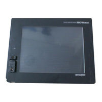
Mitsubishi Electric GT16 Connection Manual (864 pages)
GOT1000 Series
Brand:
Mitsubishi Electric
| Category:
Touch terminals
| Size: 41.7 MB
Table of Contents
Introduction
11
Safety Precautions
3
Table of Contents
11
Manuals
23
Quick Reference
25
Abbreviations and Generic Terms
27
How to Read this Manual
32
Preparatory Procedures for Monitoring
35
Setting the Communication Interface
37
Setting Connected Equipment (Channel Setting)
38
I/F Communication Setting
47
Precautions
49
Writing the Project Data and os Onto the GOT
50
Checking the Project Data and os Writing on GOT
51
Communication Module
52
Option Devices for the Respective Connection
52
Option Unit
53
Conversion Cables
53
Connector Conversion Adapter
53
Serial Multi-Drop Connection Unit
53
RS-232/485 Signal Conversion Adapter
53
Installing a Unit on Another Unit (Checking the Unit Installation Position)
54
Connection Cables for the Respective Connection
61
GOT Connector Specifications
61
Coaxial Cable Connector Connection Method
64
Terminating Resistors of GOT
65
Setting the RS-232/485 Signal Conversion Adaptor
68
Verifying GOT Recognizes Connected Equipment
69
Checking for Normal Monitoring
74
Check on the GOT
74
Confirming the Communication State on the GOT Side (for Ethernet Connection)
80
Confirming the Communication State to each Station (Station Monitoring Function)
82
Check on GX Developer
85
Check on GX Works2
89
Check on the PLC
90
Mitsubishi Electric Plc Connections
91
Device Range that Can be Set
94
MELSEC Iq-F
94
MELSEC Iq-R, Rnmt
94
Melsec-L
95
MELSEC-Qna/Q/Qs, MELDAS C6
95
MELSEC-Qnu/DC, Q17Nd/M/Nc/Dr, Crnd-700
95
MELSEC-Q (Multi)/Q Motion
105
Melsec-A
106
Melsec-Fx
107
Melsec-Ws
108
Access Range for Monitoring
111
Access Range for Monitoring
112
Access Range for Monitoring Stations on Network Systems
112
MELSECNET/H, MELSECNET/10, CC-Link IE Controller Network, CC-Link IE Field Network
112
Access Range for Monitoring When Using Ethernet Connection
123
CC-Link System Access Range for Monitoring
124
Data Link System (MELSECNET/B, (II)) Access Range for Monitoring
127
Access Range for Monitoring When Connecting FXCPU
128
Connection to Remote I/O Station in MELSECNET/H Network System
129
Connection to the Head Module of CC-Link IE Field Network System
132
System
135
How to Monitor Reduntant System
135
Connection to Remote I/O Station in MELSECNET/H Network System
142
Direct Connection to Cpu
142
Direct CPU Connection (Direct CPU Connection to the Remote I/O Station)
142
Computer Link Connection
143
Computer Link Connection (Connection to Serial Communication Module Mounted on Remote I/O Station)
143
Ethernet Connection
144
Ethernet Connection (Connection to Ethernet Module Mounted on Remote I/O Station)
144
Direct CPU Connection
145
When Using One GOT
145
When Using Two Gots
146
Precautions When Connecting a GOT Directly to a PLC CPU in the Redundant System Without Making Q Redundant Setting
147
CC-Link Connection (Intelligent Device Station)
152
CC-Link Connection (Via G4)
154
MELSECNET/H and MELSECNET/10 Connections (Network Systems)
156
CC-Link IE Controller Network Connection (Network System)
157
System
157
Ethernet Connection
158
Computer Link Connection (Connection to the Serial Communication Module Mounted on the Redundant Type Extension Base Unit)
159
Connection to the Redundant Type Extension Base Unit
159
Ethernet Connection
160
Ethernet Connection (Connection to the Ethernet Module Mounted on Redundant Type Extension Base Unit)
160
CC-Link Connection (Intelligent Device Station) (Connection to the CC-Link Module Mounted on Redundant Type Extension Base Unit)
161
CC-Link Connection (Via G4) (Connection to the CC-Link Module Mounted on Redundant Type Extension Base Unit)
162
Q Redundant Setting
162
Q Redundant Setting
163
Function
165
Method for Using the Station Number Switching Function
165
Switch the Monitor Target to the Control System Using the Script
165
Switch the Monitor Target to the Control System Using the Script Function
165
Method for Using the Screen Changing Function
172
Bus Connection
177
Connectable Model List
178
Connecting to QCPU
183
System Configuration
183
Connecting to Qnacpu or Ancpu
187
Connection to Qnascpu or Anscpu
190
Connection to A0J2HCPU
196
Connection to Motion Controller CPU (A273UCPU, A273UHCPU(-S3), A373UCPU(-S3))
197
Connecting to Motion Controller CPU (A171SCPU(-S3(N)), A171SHCPU(N), A172SHCPU(N), A173UHCPU(-S1))
202
Communication Detail Settings
208
GOT Side Settings
208
Setting Communication Interface (Communication Settings)
208
Gt15-C [ ] Exss-1, Gt15-C [ ] Bs
212
Precautions
212
Turning the GOT on
212
Position of the GOT
213
Powering off or Resetting the PLC
213
Powering off the GOT, Reapplying the Power (off to ON)
213
Reset Switch on GOT
213
When the GOT Is Bus-Connected to a PLC CPU Without the Communication Driver Written
213
When Assigning GOT I/O Signals
214
When Connecting to a QCPU (Q Mode)
214
When Designing the System
214
When Connecting to a Qna(S)CPU or an(S)CPU Type
215
When Connecting Multiple Gots
216
When Using a PLC CPU in the Direct Mode
216
Troubleshooting
217
When Connecting to a Q4ARCPU Redundant System
217
When Monitoring the Q170MCPU
217
Direct Connection to CPU
219
Connectable Model List
220
Connecting to QCPU
225
System Configuration
225
Connecting to LCPU
226
Connecting to Qnacpu
228
Connecting to ACPU
229
Connecting to MELSEC Iq-F Series
230
Connecting to FXCPU
233
Connecting to the Motion Controller CPU
243
Connecting to WSCPU
243
Cable
245
Connection Diagram
245
Cable
246
RS-422 Cable
246
Communication Detail Settings
248
GOT Side Settings
248
Setting Communication Interface (Communication Settings)
248
GX Works2 Settings
251
L6ADP-R4 Adapter Settings
251
PLC Side Setting
251
Precautions
252
Computer Link Connection
255
Connectable Model List
256
Plc/Motion Controller CPU
256
Serial Communication Module/Computer Link Module
261
Connecting to MELSEC Iq-R Series
262
System Configuration
262
Connecting to QCPU (Q Mode)
263
Connecting to LCPU
264
Connecting to QCPU (a Mode)
265
Connecting to Qnacpu (Qnacpu Type)
266
Connecting to Qnacpu (Qnascpu Type)
267
Connecting to ACPU (Ancpu Type)
269
Connecting to ACPU (Anscpu Type, A0J2HCPU, A2CCPUC)
270
Cable
271
RS-422 Cable
273
Connection Diagram
271
Communication Detail Settings
275
GOT Side Settings
275
Setting Communication Interface (Communication Settings)
275
Connecting Serial Communication Module (MELSEC Iq-R Series)
278
PLC Side Setting
278
Connecting Serial Communication Module (Q, L Series)
279
Connecting Serial Communication Module (Qna Series)
280
Connecting Computer Link Module
282
Precautions
285
Ethernet Connection
287
Connectable Model List
288
Plc/Motion Controller CPU
288
Ethernet Module
293
Connection to Ethernet Module
294
System Configuration
294
Connection to Built-In Ethernet Port CPU or C Controller Module
298
Connecting to Display I/F
300
Connection to CC-Link IE Field Network Ethernet Adapter Module
301
Connecting to PERIPHERAL I/F (Built-In Ethernet Port Motion Controller CPU)
302
Communication Detail Settings
303
Ethernet Setting
305
GOT Side Settings
303
Setting Communication Interface (Communication Settings)
303
PLC Side Setting
308
Connecting to Built-In Ethernet Port CPU (One-To One Connection)
309
Ethernet Setting
309
PLC Side Setting
309
Connecting to Built-In Ethernet Port CPU (Multiple Connection)
310
Connecting to Ethernet Module (MELSEC Iq-R Series)
312
Connection to C Controller Module (MELSEC Iq-R Series)
315
Connecting to Built-In Ethernet Port CPU (One-To-One Connection)
317
Connecting to Built-In Ethernet Port CPU (Multiple Connection)
319
Connecting to Ethernet Module (Q/L Series)
321
Connecting to C Controller Module (Q Series)
324
Connecting to Ethernet Module (Qna Series)
327
Connecting to Ethernet Module (a Series)
330
Connecting to Ethernet Module (FX Series)
335
Connecting to Built-In Ethernet Port FXCPU (FX3GE)
339
Connecting to Display I/F (CNC C70)
341
Connecting to CC-Link IE Field Network Ethernet Adapter Module
343
Connecting to PERIPHERAL I/F (Built-In Ethernet Port Motion Controller CPU)
345
Precautions
348
Related Products
Mitsubishi Electric GT1675
Mitsubishi Electric GT1685
Mitsubishi Electric GT1695
Mitsubishi Electric GT1672
Mitsubishi Electric GT1665
Mitsubishi Electric GT1662
Mitsubishi Electric GT1655
Mitsubishi Electric GT1695M-XTBD
Mitsubishi Electric GT1685M-STBA
Mitsubishi Electric GT1685M-STBD
Mitsubishi Electric Categories
Air Conditioner
Controller
Projector
Inverter
Heat Pump
More Mitsubishi Electric Manuals