beautypg.com
Manuals
Brands
National Semiconductor Manuals
Motherboard
TSW3070EVM
National Semiconductor TSW3070EVM Manuals
Manuals and User Guides for National Semiconductor TSW3070EVM. We have
1
National Semiconductor TSW3070EVM manual available for free PDF download: User Manual
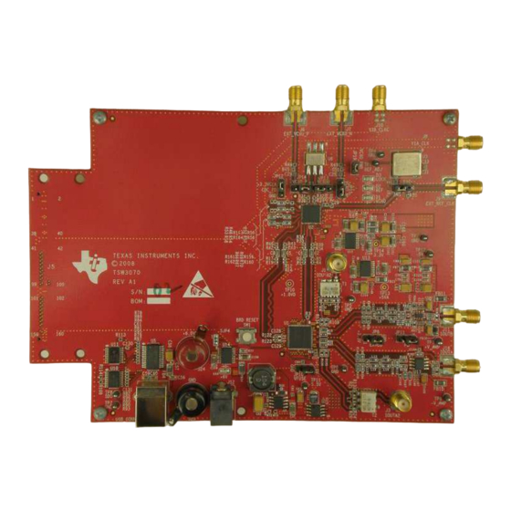
National Semiconductor TSW3070EVM User Manual (32 pages)
Amplifier Interface to Current Sink DAC - Arbitrary Waveform Generator Demonstration
Brand:
National Semiconductor
| Category:
Motherboard
| Size: 1.55 MB
Table of Contents
Table of Contents
1
TSW3070EVM Configuration Options
3
DAC Component
3
Board Configuration
3
Vcxo
3
Block Diagrams
4
System Block Diagram
4
Key Texas Instruments Components
4
Cdcm7005
4
Dac5682Z
4
Tps76Xxx, TPS5430, UCC284-5
4
Block Diagram
4
Opa695, Ths3091, Ths30915
5
DAC5682Z USB Control Software Installation
5
DAC5682Z EVM Driver Installation
8
Software Boxes
10
Home Menu Showing EVM Status
10
Software Main Settings
10
Software Box Descriptions
10
DAC5682Z Register Configuration and Block Diagram Menu
11
DAC5682Z Register and CDCM7005 Configuration Menu
12
Complete Software Overview
13
DAC5682Z Register Configuration and TSW3100 Pattern Generator Control Menu
13
TSW3070EVM Introduction
17
Jumper Settings
17
Input and Output Connectors
17
USB Interface
18
Power Management
18
Demonstration Kit Test Configuration Test Equipment 7.1 Test
18
Test Setup
18
Test Equipment
18
TSW3070EVM Driven by TSW3100 Pattern Generator
18
Typical Performance Measurements
19
Typical THS3091 and THS3095 Voltage Output, Default Gain 3.3X
19
THS3091 and THS3095 with ±15-V External Supplies, 50-Ω Input, Gain at 10X
19
THS3091 and THS3095 LPF Filter Shape Evaluated with Multi-Tone Input Signal from the TSW3100 Pattern Generator
20
OPA695 LPF Filter Shape Evaluated with Multi-Tone Signal
20
IMD3 Plot for THS3095
21
IMD3 Plot for OPA695
21
Summary of IMD3 for Passive Transformer, OPA695, THS3091, and THS3095 Output
22
Summary of Harmonic Distortion for Passive Transformer, OPA695, THS3091, and THS3095 Output
22
Initial Power up and Test
23
Initial Inspection
23
Engage Power Supplies
23
Verify Status of the Board
23
Program the CDCM7005
23
CDCM7005, 800M VCXO, 10M Ref, Locked Condition Leds
23
Program the DAC5682Z
24
Program TSW3100
24
DAC5682 and CDCM7005 Example Register Settings
24
Optional Configurations
25
External VCXO
25
Transformer Passive Output
25
DAC5682Z Resistor Jumper Configuration
25
Higher Amplifier Voltage Supplies
26
Position of Ferrite Beads for Power Options
26
Baseband Filter
27
Schematic, Bill of Materials and Printed-Circuit Board Layout
27
10.1 Design Resources
27
Related Products
National Semiconductor TPS736
National Semiconductor TPS5430
National Semiconductor THS3095
National Semiconductor THS3091
National Semiconductor TPS65132S
National Semiconductor TPS65132SEVM-866
National Semiconductor TPS65132L
National Semiconductor TPS65132
National Semiconductor TPS7A8300
National Semiconductor TPS737
National Semiconductor Categories
Motherboard
Computer Hardware
Amplifier
Controller
Microcontrollers
More National Semiconductor Manuals