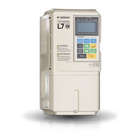
Omron L7 Manuals
Manuals and User Guides for Omron L7. We have 4 Omron L7 manuals available for free PDF download: Manual, Datasheet, Brochure & Specs
OMRON L7 Manual (299 pages)
Table of Contents
-
Warnings8
-
Line Filters13
-
-
2 Wiring
32-
Wiring Check54
-
Checks54
-
-
-
-
Start up77
-
-
Power up78
-
Autotuning79
-
-
-
-
-
Field Forcing189
-
-
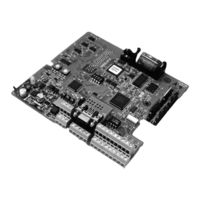
PG Option Cards223
-
PG Setup223
-
Fault Detection225
-
-
Rescue System228
-
-
Troubleshooting263
-
9 Specifications
274 -
10 Appendix
288

OMRON L7 Brochure & Specs (4 pages)
VARISPEED L7 Series
