beautypg.com
Manuals
Brands
Panasonic Manuals
Touch terminals
GTWIN
Panasonic GTWIN Manuals
Manuals and User Guides for Panasonic GTWIN. We have
4
Panasonic GTWIN manuals available for free PDF download: Reference Manual, User Manual, Manual
Panasonic GTWIN Reference Manual (297 pages)
Brand:
Panasonic
| Category:
Touch terminals
| Size: 9.74 MB
Table of Contents
Table of Contents
4
1 Introducing GTWIN
11
Overview of GTWIN
12
Windows Vista
13
Booting GTWIN
14
Read from GT
15
GT Memory Editor
16
Upload Alarm History Information
16
Edit GT Internal Memory
17
Upload Line Graph Information
17
GT Ver_Up
17
Modem Connection
18
Create New File
19
GTWIN Configuration
20
GT Configuration
22
Basic Setup
24
Basic Communication Area to PLC
25
Communication Parameters
27
PLC Multiple Connection
29
Skip Communication Error Station
30
PLC Unit No. and Comment
31
Auto-Paging
32
Start-Up Screen
32
Setup 1
33
Summer Time
36
Setup 2
36
Countdown Timer
38
Hold Device Value
39
Recipe
40
Recipe Control
42
Alarm History Setting
42
Alarm History Control
45
Save Alarm Data on SD Memory Card
47
Line Graph
49
Line Graph Control
51
Sound
52
Operation Security
53
GT Link
54
How GT Link Functions
56
Index Registration
57
2 GT Panel System Menu
59
GT Panel System Menu Overview
60
Port
62
Clear Memory
63
Test Menu
65
DIP Switch Settings to Prevent System Menu Display
66
SD Memory Card Functions
67
Usable SD Memory Cards
69
Restrictions
70
Copy Screen Data to the SD Memory Card
72
Copy Screen Data to the GT
74
Copy PLC Program Files to the PLC
75
Copy PLC Program Files to the SD Memory Card
77
Delete Data from the SD Memory Card
79
FP Monitor
81
Installing FP Monitor on the GT
81
Uninstalling FP Monitor
83
Using FP Monitor
84
Error Monitor Screen
85
System Register Monitor Screen
85
Device Monitor Screen
86
Password Management Screen
91
Shared Memory Monitor Screen
93
3 The GTWIN User Interface
94
What You See on Your Monitor
95
Menu Bar
96
Toolbar
97
Graphic Bar
99
Size/Coordinate Bar
102
Base Screen
103
Parts Library
104
New Parts Library
105
Flowchart Symbols Library
106
Screen Manager
107
4 Menus
108
File Menu
109
New, Open, Close, Save, Save As, Delete
109
Windows Fonts Not Available
110
Print
111
Print Style Setup
112
Printer Setup
113
Transfer
114
Configuration
115
Keyboard Screen
116
Login Screen
117
Utility
117
PLC Model Convert
118
GT Model Convert
119
Convert Fixed (GTWIN) Font
120
Change Device
123
Edit Menu and Common Editing Functions
125
Multiple Copy
126
View Menu
127
Draw Menu
128
Base Screen Menu
129
Parts Menu
130
Start Editor Menu
132
Bitmap
132
How to Create a Bitmap with the Bitmap Editor
133
Using the Bitmap Editor
135
Importing Bitmap Files
137
Organizing Bitmap Files
138
Placing Bitmaps on Base Screens
138
Recipe
140
How to Create a Recipe File
140
Example Recipe
143
Transferring Recipe Files
143
SD Recipe
146
How to Save SD Recipe Data on the SD Memory Card
147
SD Recipe Basic Setup
148
Specify File No. by Control Device
149
Specify Recipe File Name by Touch Operation
149
SD Recipe Recipe Setting
150
Entering and Reading Device Values
151
Handshake Using Write Device
152
Flow Display
153
Write Device
155
Sound
157
Operation Security Password
159
Multi-Language Exchange String List
160
Setup with the String List
161
Setup for Individual Parts
164
Change the Language with a Function Switch
167
Change the Language with a PLC
169
Data Logging
170
Log File and CSV File Structure
172
Log File Setup
174
Control Setup for Data Logging
177
Window Menu
180
Help Menu
181
5 Parts and Their Functions
182
Switch Parts
183
Function Switch Parts
185
Multi Function
188
Lamp Parts
189
Message Parts
191
Message Part, Sample FPWIN Pro Program
192
Data Parts
195
Basic Setup for Data Parts
196
Input Settings for Data Parts
198
Bar Graph Parts
200
Clock Parts
202
Alarm List Parts
203
History of Alarms in Time Order
204
History of Alarms in Order of Frequency
206
List of Active Alarms
207
Line Graph Parts
209
Configuration Parameters
209
Display Data" Options on "Display" Tab
210
Line Settings" Tab When "Reference Data" = "Device" (Basic Setup)
211
Line Settings" Tab When "Reference Data" = "SD Card (Logging Data)" (Basic Setup)
212
Comparing Line Graph Modes
213
Basic Setup in Sampling Mode
216
Basic Setup in Block Mode
218
Line Graphs Combined with Bar Graphs
221
Keyboard Parts
224
Basic Setup for Keyboard Parts
225
Operation Setup for Keyboard Parts
227
Displaying and Hiding Keyboard Parts
227
Custom Parts
228
Custom Switch Parts
228
Custom Lamp and Custom Message Parts
229
Replacement Tab for Custom Parts
231
6 Troubleshooting
234
Troubleshooting
235
Screen Messages
236
GT Series Error Codes
237
PLC Error Codes
240
General-Purpose Serial Communication Error Codes
243
What to Do if Something Unusual Occurs
244
Operation Security Function
247
7 Connecting the GT to a PLC
248
Panasonic FP-Series Plcs
249
PLC Multiple Connection
251
Cautions Regarding Connecting the 5V DC Type
253
Connecting the 5V Type to the TOOL Port of a Compact PLC
254
Connecting 24V Types to the TOOL Port of a Compact PLC
256
Connecting the 5V Type to the TOOL Port of FP2/FP2SH
258
Connecting 24V Types to the TOOL Port of FP2/FP2SH
260
Connecting to the COM Port of FP-X
262
Connecting to the COM Port of FPΣ/FP0(R)/FP-E
266
Connecting to the COM Port of FP2/FP2SH
270
Connecting to the FP2/FP2SH Computer Communication Unit
272
Connecting to the C-NET ADAPTER
274
Connecting Via GT Link
275
GT Link Using FP2/FP2SH
275
GT Link Using FP-X
278
GT Link Using FPΣ
283
8 SD Card Data Upload from GT to PC
288
Introduction to the Gt_Sd_Reader
289
Working with Gt_Sd_Reader
290
Glossary of Terms
294
Panasonic GTWIN Reference Manual (239 pages)
Brand:
Panasonic
| Category:
Touch terminals
| Size: 7.09 MB
Table of Contents
Table of Contents
4
1 Introducing GTWIN
10
Overview of GTWIN
11
Windows
13
Booting GTWIN
14
Read from GT
15
GT Memory Editor
16
Upload Alarm History Information
16
Upload Line Graph Information
17
Edit GT Internal Memory
17
GT Ver_Up_V3
18
Create New File
19
2 The GTWIN User Interface
20
What You See on Your Monitor
21
Menu Bar
24
Toolbars
25
Base Screen
30
Parts Library
31
Working with Parts Libraries
31
Standard Library with Parts Available for All GT Panels
33
GT02 - GT32 Libraries
34
GT703/GT704/GT707 Libraries
35
Flowchart Symbols Library
35
Screen Manager
37
Login Screen
38
Keyboard Screen
39
System Setting
41
3 GT Panel System Menu
42
GT Panel System Menu Overview
43
Port
45
COM Port
45
Ethernet Port
45
Clear Memory
47
Test Menu for GT02 - GT32
48
DIP Switch Settings to Prevent System Menu Display
49
SD Memory Card Functions
50
Usable SD Memory Cards
52
Restrictions
53
Copy Screen Data to the SD Memory Card
55
Copy Screen Data to the GT
57
Copy PLC Program Files to the PLC
58
Copy PLC Program Files to the SD Memory Card
60
Delete Data from the SD Memory Card
62
FP Monitor
64
Installing FP Monitor on the GT (Except for GT703/GT704/707
64
Uninstalling FP Monitor (Except for GT703/GT704/707
66
Using FP Monitor
67
System Register Monitor Screen
68
Error Monitor Screen
68
Device Monitor Screen
69
Password Management Screen
74
Shared Memory Monitor Screen
76
4 Menus
77
File Menu
78
New, Open, Close, Save, Save as
78
Print
79
Print Style Setup
80
Printer Setup
80
Save Screen Bitmap
80
PLC Model Convert
81
GT Model Convert
81
Convert Fixed (GTWIN) Font
82
Change Device
84
Export/Import Character String List for Multi-Language Exchange
85
SD Memory Card File
85
Edit Menu and Common Editing Functions
87
Multiple Copy
88
Find Device
88
Character String List
89
GTWIN Configuration
90
View Menu
92
Draw Menu
93
System Setting Menu
94
GT Configuration
94
Basic Setup
96
GT Communication Parameters
100
PLC Multiple Connection
101
Clock Setting
103
Multi-Language Exchange
105
GT Link
113
Recipe
116
SD Recipe
118
Operation Security
119
Auto-Paging
120
Start-Up Screen
121
SD Memory Card
122
Hold Device Value
122
Alarm History and Alarm History Setting
123
Line Graph
128
Index Registration
130
Countdown Timer
131
Flow Display
132
Write Device
133
Data Logging
135
Log File and CSV File Structure
137
Log File Setup
138
Record Area Control for Data Logging
140
Recipe List
142
How to Create a Recipe File
142
Transferring Recipe Files
144
SD Recipe
145
How to Save SD Recipe Data on the SD Memory Card
146
SD Recipe Basic Setup
147
Specify File No. by Control Device
148
Specify Recipe File Name by Touch Operation
148
SD Recipe Recipe Setting
149
Entering and Reading Device Values
150
Handshake Using Write Device
151
Operation Security Password
152
Communication
153
Window Menu
156
Help Menu
157
5 Parts and Their Functions
158
Switch Parts
159
Operation Modes
159
GT02 - GT32 Switch Parts
161
Normal Switch Parts
163
Function Switch Parts
165
GT703/GT704/GT707 Switch Parts
168
Changing the Design of Parts
170
Lamp Parts
174
Message Parts
177
Data Parts
182
Basic Setup for Data Parts
184
Input Settings for Data Parts
186
Bar Graph Parts
188
Clock Parts
190
Alarm List Parts
191
History of Alarms in Time Order
192
History of Alarms in Order of Frequency
194
List of Active Alarms
195
Line Graph Parts
197
Configuration Parameters
197
Display Data" Options on "Display" Tab
198
Line Settings" Tab When "Reference Data" = "Device" (Basic Setup)
199
Line Settings" Tab When "Reference Data" = "SD Card (Logging Data)" (Basic Setup)
200
Comparing Line Graph Modes
201
Basic Setup in Sampling Mode
203
Basic Setup in Block Mode
206
Line Graphs Combined with Bar Graphs
209
Keyboard Parts
211
Basic Setup for Keyboard Parts
212
Operation Setup for Keyboard Parts
214
Displaying and Hiding Keyboard Parts
214
Custom Parts
216
6 Troubleshooting
217
Troubleshooting
218
Screen Messages
219
GT Series Error Codes
220
PLC Error Codes
223
General-Purpose Serial Communication Error Codes
226
What to Do if Something Unusual Occurs
227
Operation Security Function
230
7 SD Card Data Upload from GT to PC
231
Introduction to the Gt_Sd_Reader
232
Working with Gt_Sd_Reader
233
8 Glossary of Terms
236
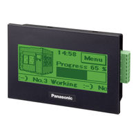
Panasonic GTWIN User Manual (181 pages)
GT series Programmable Display
Brand:
Panasonic
| Category:
Monitor
| Size: 4.63 MB
Table of Contents
Safety Precautions
2
Table of Contents
3
Before You Start
9
Manual to be Used
11
Available Functions and GT Versions
12
Chapter 1 Features and Functions
23
Features and Functions of GT Series
24
Types of Units
29
GT Series
29
Options and Repair Parts
31
Screen Creation Tool
34
Tools Required for Screen Creation
34
Software Usage Environment and Applicable Cables
34
Chapter 2 Names and Functions of Parts
37
Part Names
38
GT01, GT11 and GT21
38
Gt02/Gt02L
40
Gt05/Gt12/Gt32
42
Terminal Layouts of COM Port
44
Gt01
44
Gt02
45
Gt02L
46
Gt11/Gt12
47
Gt21
48
Gt05/Gt32/Gt32-E
49
Connecting to Screen Creation Tool GTWIN
50
TOOL Port
50
USB Port
50
Ethernet Port
51
Chapter 3 Installation and Wiring
55
Installation
56
Installation Environment
56
Restriction According to Mounting Directions
58
Installation Space
58
Ul/C-UL Qualification
58
Mounting Screws
59
GT01 and GT11 Installation Method
60
GT21 Installation Method
60
GT05/GT32/GT32-E Installation Method
61
GT02/GT02L/GT12 Installation Method
62
Installing in Vertical Orientation
63
Precaution When Reinstalling GT
63
Wiring the Power Supply
64
Grounding
65
Wiring the COM Port
66
Precautions When Wiring COM Port
68
Gt01 (5 V DC)
68
Gt02/Gt02L (5 V DC)
69
RS232C Communication
70
RS422 (RS485) Communication
71
Precautions When Wiring Ethernet Port (GT32T1)
72
Options
73
Backup Battery
73
How to Install the Battery (Lithium Button Battery)
74
How to Install the Battery (Backup Battery)
74
Dead Battery Mark
75
Time for Replacement of Battery
75
Replacement of Front Panel Protective Sheet
75
About the Waterproof Packing
76
Chapter 4 Connecting with PLC
77
Connection with PLC
78
PLC Multiple Connection
78
GT Link Connection
78
Connecting to the Plcs Made by Other Companies
79
Connecting to a Serial Device
79
Electric Supply from PLC (5 V DC-Type )
79
RS232C Connection
80
Difference of Terminal Blocks between GT Models
80
RS232C Connection with PLC Tool Port
81
RS232C Connection with FP-X COM Port
83
RS232C Connection with FP COM Port
85
RS232C Connection with FP0/FP0R COM Port
87
RS232C Connection with FP-E COM Port
88
RS232C Connection with FP2/FP2SH COM Port
89
RS422 Connection
90
Difference of Terminal Blocks between GT Models
90
RS422 Connection with FP-X COM Port
91
RS422 Connection with FP2/FP2SH COM Port
92
RS422 Connection with C-NET Adapter
93
RS485 Connection
94
Difference of Terminal Blocks between GT Models
94
RS485 Connection with FP0R COM Port
95
RS485 Connection with FP-X COM Port
96
RS485 Connection with FPΣ COM Port
99
RS485 Connection with FP-E COM Port
101
Rs485Connection with FP2/FP2SH
102
Precautions When Communicating with RS485
103
Connection with a PLC
104
Automatic Communication Settings Function
104
Through Function
105
How to Make Communication Settings Using the FPWIN GR
107
Chapter 5 Troubleshooting
109
What to DO if Something Unusual Occurs (GT01/GT11/ GT21)
110
Troubleshooting
110
What to DO if Something Unusual Occurs (GT02/GT02L/GT05/GT12/GT32)
113
Error Codes and How to Handle Them
118
About Error Codes
118
GT Series Error Codes
118
When Connected to a FP Series PLC
121
When Connected to a PLC (FX Series) Made by Mitsubishi Electric Corporation
123
When Connected to a PLC Made by Omron Corporation
124
When Connected to Modbus
125
When Connected to a PLC Made by Toshiba Machine Co., Ltd
125
When Performing General-Purpose Serial Communication
126
Chapter 6 Specifications
127
Gt01
128
General Specifications
128
Performance Specifications (GT01)
129
Function Specifications (GT01)
130
Interface Specifications (GT01)
131
Gt02
132
General Specifications (GT02)
132
Performance Specifications (GT02)
133
Function Specifications (GT02)
134
Interface Specifications (GT02)
135
Gt02L
136
General Specifications (GT02L)
136
Performance Specifications (GT02L)
137
Function Specifications (GT02L)
138
Interface Specifications (GT02L)
139
Gt05
140
General Specifications
140
Performance Specifications (GT05)
141
Function Specifications (GT05)
142
Interface Specifications (GT05)
143
Gt11
144
General Specifications (GT11)
144
Performance Specifications (GT11)
145
Function Specifications (GT11)
146
Interface Specifications (GT11)
147
Gt12
148
General Specifications (GT12)
148
Performance Specifications (GT12)
149
Function Specifications (GT12)
150
Interface Specifications (GT12)
151
Gt21
152
General Specifications (GT21)
152
Performance Specifications (GT21)
153
Function Specifications (GT21)
154
Interface Specifications (GT21)
155
Gt32
156
General Specifications (GT32)
156
Performance Specifications (GT32)
157
Function Specifications (GT32)
158
Interface Specifications (GT32)
159
Sound Output Specifications (GT32T1 Only)
160
Gt32-E
161
General Specifications (GT32-E)
161
Performance Specifications (GT32-E)
162
Function Specifications (GT32-E)
163
Interface Specifications (GT32-E)
164
Chapter 7 Dimensions and Other Documentation
165
Dimensions
166
Gt01/Gt01R
166
Gt02
167
Gt02L
168
Gt05
169
Gt11
170
Gt12
171
Gt21
172
Gt32-E
174
Cable Specifications
175
Aigt8142
175
Aigt8152
175
Aigt8162/Aigt8165/Aigt8160
175
Aigt8175
176
Aip81842
176
Table of Screen Messages
177
BIN/HEX/BCD Code Correspondence Table
178
ASCII Code Table
179
Record of Changes
181
Panasonic GTWIN Manual (136 pages)
Connection with other companies’ PLCs
Brand:
Panasonic
| Category:
Monitor
| Size: 8.73 MB
Table of Contents
Table of Contents
3
Applicable Plcs Manufactured by Various Companies
7
Selecting the PLC Model
12
1 Connection with Mitsubishi Plcs
13
MELSEC-FX1S/ FX1N/ FX1NC Series
14
Direct Connection to the TOOL Port
15
Using an Adapter
16
MELSEC-FX2N/ FX2NC/ FX3U/ FX3UC/ FX3G / FX3GC Series
17
Direct Connection to the TOOL Port
19
Using an Adapter
20
MELSEC-L (Serial Communication) Series
21
MELSEC-L (Serial Communication) Series
24
MELSEC-L (Serial Communication) Series (RS422)
24
MELSEC-L (CPU) Series
25
MELSEC-L (CPU) Series
28
MELSEC-Q (Serial Communication) Series
29
MELSEC-Q (Serial Communication) Series (RS232C)
32
MELSEC-Q (Serial Communication) Series (RS422)
32
When Directly Connecting to the RS232C Port of Q00CPU/ Q00UJCPU/ Q01CPU
33
MELSEC-Q (CPU) Series
34
MELSEC-A (Computer Link) Series
36
2 Connection with Omron Plcs
39
Omron SYSMAC-C Series (C/Α/CV/Cp1)
40
SYSMAC C Series (Using Link Interface) (RS232C)
43
SYSMAC Α Series (Using Link Interface) (RS232C)
46
SYSMAC CV Series (Using Link Interface) (RS232C)
47
SYSMAC CP1 Series (Using Link Interface) (RS232C)
48
SYSMAC CP1 Series (RS422/RS485)
49
SYSMAC CP1 Series (Built-In RS232C Port Type)
49
When Using the Peripheral Port of CPM2C
50
Omron SYSMAC-CS/CJ Series
52
SYSMAC CS1 Series (1:1) (RS232C)
56
SYSMAC CJ1 Series (1:1) (RS232C)
57
SYSMAC CS1/CJ1 Series (1:1) (RS422/RS485)
58
SYSMAC CJ2M Series (1:1) (RS232C)
59
SYSMAC CJ2M Series (RS422/RS485)
59
When Using the Peripheral Port
60
3 Connection with Toshiba Machine Plcs
63
PROVISOR Tcmini Series
64
RS232C Connection
65
RS485 Connection
66
4 Connection with Rockwell Automation (Allen-Bradley) Plcs
67
Allen-Bradley SLC500 Micrologix Series
68
SLC500 Series(Using Link Interface on the CPU Unit)
71
Micrologix1000/1100
72
5 Connection with Siemens Plcs
73
Siemens S7-200 Series
74
RS232C Connection (Connected with PC/PPI Cable)
75
RS422 Connection
76
6 Connection with LS Industrial Systems Plcs
77
MASTER-K (Cnet) Series
78
Connection Method
79
7 Connection with Yokogawa Plcs
81
FA-M3 Series
82
Connection Using PC Link Module
84
CPU Direct Connection
85
8 Connection with Keyence Plcs
87
KV-10/16/24/40 Series
88
Series
88
KV-700 Series
90
Connection Method
91
Series Connected Using Unit KV-L20R/V
92
Connection Method
93
KV-1000 Series
94
Connection Method
95
KV-1000 Series Connected Using Unit KV-L20R/V
96
Connection Method
98
KV-3000 Series
99
Connection Method
100
KV-3000/5000 Series Connected Using Unit KV-L20R/V
101
Connection Method
103
KV Nano Series
104
Connection Method
105
KV Nano Series Connected Using Unit KV-L20R/V
106
Connection Method
108
9 Connection with Hitachi Plcs
109
EH-150/EHV Series
110
RS232C Connection
113
RS422 Connection
117
RS485 Connection
118
MICRO-EH Series
119
RS232C Connection
121
Web Controller Series
123
RS232C Connection
125
RS422 Connection
127
RS485 Connection
128
10 Connection in Modbus (RTU Mode)
129
Modbus (RTU Mode | Modicon PLC)
130
Modbus (RTU Mode)
131
Modbus (RTU Mode) for Temperature Control Unit, Etc
132
Connection Method (Example)
134
Record of Changes
135
Related Products
Panasonic GT02
Panasonic GT03-E
Panasonic GT12
Panasonic GT32
Panasonic GT32-E
Panasonic GT707
Panasonic GT21C
Panasonic GT32M/T
Panasonic GT series
Panasonic GT703
Panasonic Categories
Air Conditioner
Camcorder
TV
Digital Camera
Cordless Telephone
More Panasonic Manuals