beautypg.com
Manuals
Brands
Parker Manuals
Controller
690+ series
Parker 690+ series Manuals
Manuals and User Guides for Parker 690+ series. We have
7
Parker 690+ series manuals available for free PDF download: Product Manual, Safety & Quickstart, Quick Start, Quick Start Manual
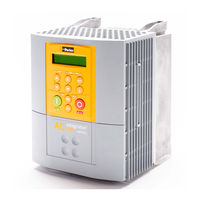
Parker 690+ - Flux Sensorless Vector Quick Start Manual
Brand:
Parker
| Category:
Inverter Drive
| Size: 0.29 MB
Table of Contents
BEFORE YOU START
CONTROL MODES
POWER CONNECTIONS
REFERENCE
SEQUENCING
SPEED FEEDBACK
CALIBRATION
AUTOTUNE
VIEW LEVELS
MACROS
INTERNAL LINKS
TECHNOLOGY BOXES
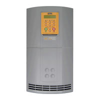
Parker 690+ series Product Manual (171 pages)
Brand:
Parker
| Category:
Controller
| Size: 4.24 MB
Table of Contents
Table of Contents
5
Etting
11
S T a R T E D Introduction
11
Equipment Inspection
11
Packaging and Lifting Details
12
About this Manual
12
How the Manual Is Organised
12
Information for Users Without a Keypad
13
Initial Steps
12
Drive
16
Introduction
16
Component Identification
18
Product Range
19
Equipment Supplied
19
Control Features
20
Functional Overview
21
Handling the Drive
24
Nstalling the
24
Rive
24
Ventilation
24
Air Flow
24
Mounting the Drive
25
Fitting the External Vent Kit (Frame G)
26
Fitting the External Vent Kit (Frames H & J)
27
Fitting the Main Cooling Fan (Frame J)
28
Cable Tray and Cover
29
Mechanical Installation
24
Electrical Installation
29
Removing the Terminal Cover
29
Chapter 1 Wiring Scheme
30
Connections
31
Power Terminals
31
Motor Thermistor Terminals
31
Control Terminals
33
AC Line Choke (Input)
34
Mandatory Equipment
34
Output Sharing Choke
37
Rating Guidelines for Output Sharing Chokes
39
Optional Equipment
41
System Board
41
Encoder Connections
42
Parker SSD Drives Approved Encoders
42
Technology Options
43
Fitting the Remote 6901/6911 Keypad
44
Dynamic Braking Option
45
External AC Supply Filter
47
Output Contactors
50
Earth Fault Monitoring Systems
50
5703/1 Speed Repeater Support
50
Installation Drawings
52
Chapter 4 OPERATING the DRIVE
62
Pre-Operation Checks
62
Control Philosophy
63
Start/Stop and Speed Control
63
Selecting Local or Remote Control
64
Initial Start-Up Routines
65
Routine 1: Remote Control Using Control Terminals
65
Reading the Status Leds
65
Routine 2: Local Control Using the Keypad
66
Drive Set-Up
66
Set-Up as an Open-Loop Drive (V/F Fluxing)
67
Set-Up Using the Sensorless Vector Fluxing Mode
67
Set-Up Using the Closed-Loop Vector Mode
68
The Autotune Feature
68
Stationary or Rotating Autotune
69
Necessary Data
69
Performing a Rotating Autotune
69
Performing a Stationary Autotune
70
Setting the Encoder Sign
70
The Start/Stop Mode Explained
71
Starting and Stopping Methods
72
Normal Stopping Methods
72
Ramp to Stop
73
Coast to Stop
73
Advanced Stopping Methods
74
Forced Fast Stop
74
Forced Coast Stop
74
The Trip Condition
74
Logic Stopping
75
Starting Methods
75
Starting Several Drives Simultaneously
76
Single Wire Logic Starting
76
Two Wire Logic Starting
76
Three Wire Logic Starting
76
Chapter 3 Connecting the Keypad
78
The Power-Up Condition
78
Chapter 5 THE KEYPAD
78
Controlling the Drive Using the Keypad
79
Control Key Definitions
79
Keys for Programming the Drive
79
Keys for Operating the Drive Locally
79
LED Indications
80
The Menu System
81
Navigating the Menu System
81
Menu Viewing Levels
81
Changing a Parameter Value
82
What Do the Symbols Mean Next to some Parameters
82
Parameter Status Information
82
Expanded Menu Information
82
Alert Message Displays
82
The Menu System Map
83
The PROG Key
85
The L/R Key
85
The OPERATOR Menu
86
Parameter Selection
86
String Entry
87
Customising the Parameter Name
87
The DIAGNOSTICS Menu
88
The QUICK SETUP Menu
92
The SYSTEM Menu
93
Saving/Restoring/Deleting Your Application
93
Selecting the Language
95
Special Menu Features
95
Quick Save Feature
95
Quick Tag Information
96
Quick Link Information
96
Password Protection
97
To Activate Password Protection
97
To De-Activate Password Protection
97
To Re-Activate Password Protection
97
To Remove Password Protection (Default Status)
97
Power-Up Key Combinations
98
Resetting to Factory Defaults (2-Button Reset)
98
Changing the Product Code (3-Button Reset)
98
Quick Enter Configuration Mode
99
Chapter 6 TRIPS and FAULT FINDING
100
Trips
100
What Happens When a Trip Occurs
100
Drive Indications
100
Keypad Indications (When Connected)
100
Resetting a Trip Condition
100
Using the Keypad to Manage Trips
101
Trip Messages
101
Automatic Trip Reset
103
Setting Trip Conditions
103
Viewing Trip Conditions
104
Checksum Fail
104
Drive Indications
104
Keypad Indications (When Connected)
104
Fault Finding
104
Troubleshooting Leds
105
Chapter 7 ROUTINE MAINTENANCE ANDREPAIR
108
Routine Maintenance
108
Repair
108
Saving Your Application Data
108
Returning the Unit to Parker SSD Drives
108
Disposal
108
Chapter 8 Electro-Mechanical Parts
109
Printed Circuit Boards
109
Spares List
109
Component Replacement
110
Printed Circuit Board (PCB) Replacement
110
Fan Replacement
113
Phase Assembly Replacement
116
Echnical Pecifications
120
Understanding the Product Code
120
Model Number (Europe)
120
Catalog Number (North America)
122
Environmental Details
124
Earthing/Safety Details
124
Cabling Requirements for EMC Compliance
125
Terminal Block Wire Sizes
125
DC Link Fuses
125
Electrical Ratings (Master + 1 Slave)
126
Electrical Ratings (Master + 2 Slaves)
127
External AC Supply (RFI) Filter
128
AC Line Choke
128
Internal Dynamic Brake Switch
129
Control Terminals
130
System Board Terminals (Master Drive Option)
131
Analog Inputs/Outputs
132
Digital Inputs
132
Digital Outputs
132
System Board Digital Inputs/Outputs (DIGIO1-5)
132
Chapter 9 CERTIFICATION for the DRIVE
134
Requirements for EMC Compliance
134
Minimising Radiated Emissions
134
Earthing Requirements
134
Protective Earth (PE) Connections
134
EMC Earth Connections
134
Cabling Requirements
135
Planning Cable Runs
135
Increasing Motor Cable Length
135
EMC Installation Options
136
Screening & Earthing (Cubicle Mounted)
136
Star Point Earthing
136
Sensitive Equipment
137
Certificates
143
Chapter 10 APPLICATION NOTES
144
Synchronous Motor Control
144
Brake Motors
144
Using Line Chokes
144
Using Output Contactors
144
Using Multiple Motors on a Single Drive
145
Dynamic Braking
145
High Starting Torque
146
Winder Applications
146
Roll Diameter Calculation Accuracy
146
Basic Set-Up Instruction
148
Information Required
148
Set-Up with no Web Connected to the Winder
149
Equations
149
Simple Centre Winder Equations
149
2-Q Common DC Bus Applications
152
4-Q Regen Control/Common DC Bus Applications
154
Introduction
154
4-Q Active Front End
155
EMC Filtering
156
Contactor and Fusing
156
Drive Set-Up
157
Macro 8 : 4Q Regen
158
A Single Motor System
159
A Multi-Motor System
160
A Smart Brake System
161
DC Link Fuses
162
Pre-Charge Sizing
163
3-Phase Choke Sizing
164
Chapter 11 THE DEFAULT APPLICATION
166
The Default Application
166
Macro Descriptions
166
Macro 1: Basic Speed Control (Default)
168
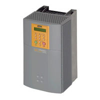
Parker 690+ series Product Manual (242 pages)
Brand:
Parker
| Category:
Controller
| Size: 1.63 MB
Table of Contents
Table of Contents
5
Introducing the Macro
9
Chapter 1 PROGRAMMING YOURAPPLICATION
9
Programming with Block Diagrams
9
Modifying a Block Diagram
9
Configuration and Parameterisation Modes
9
Making and Breaking Links in Configuration Mode
10
Programming Rules
12
Execution Rules
12
Saving Your Modifications
12
SETUP Menu - Function Block Descriptions
13
Understanding the Function Block Description
13
MMI Menu Maps
13
Function Blocks by Category
14
Function Blocks in Alphabetical Order
15
5703 Input
15
5703 Output
16
Access Control
17
Analog Input
18
Analog Output
20
Auto Restart
23
Autotune
25
Brake Control
26
Comms Control
27
Compensation
28
Current Limit
30
Demultiplexer
31
Diameter Calc
32
Digital Input
35
Digital Output
37
Display Scale
38
Dynamic Braking
40
Encoder Speed
41
Energy Meter
42
Feedbacks
43
Filter
45
Fluxing
46
Flycatching
49
Home
51
Inj Braking
53
I/O Trips
54
Inverse Time
55
Linear Ramp
56
Local Control
57
Logic Function
58
Minimum Speed
62
Motor Data
63
Multiplexer
65
Op Station
66
Operator Menu
67
Pattern Gen
70
Phase Auto Gear
71
Phase Configure
74
Phase Control
77
Phase Inch
79
Phase Move
80
Phase Offset
81
Phase Pid
82
Phase Register
84
Phase Tuning
86
Chapter 2 PID
87
Pid (Type 2)
87
Position
91
Preset
92
Chapter 3 POWER LOSS CNTRL
94
Raise/Lower
95
Reference
96
Reference Jog
98
Reference Ramp
99
Reference Stop
101
Regen Control
102
Sequencing Logic
104
Setpoint Scale
107
Skip Frequencies
108
Slew Rate Limit
110
Slip Comp
111
Spd Fbk Trip
112
Speed Calc
113
Speed Loop
115
S-Ramp
118
Stabilisation
119
Stall Trip
120
System Option
121
System Port (P3)
122
Taper Calc
123
Tec Option
126
Timer
127
Torque Calc
129
Torque Limit
130
Trips History
131
Trips Status
132
Value Function
134
Voltage Control
142
Zero Speed
143
Quadratic/Constant Torque Selection
144
Arameter Pecification
145
Specification Table: Tag Name Order
146
Specification Table: Tag Number Order
158
6053 Technology Box Dependent Parameters
185
Product-Related Default Values
185
Frequency Dependent Defaults
185
Power Dependent Defaults
185
C O M M U N I C a T I O N S Communications Technology Option
201
Configed Lite
201
Connection to the P3 Port
201
File Transfer
202
File Read (FR)
203
File Write (FW)
203
Interaction with the 6901 Operator Station
204
File Names
204
Logic
205
Principle State Machine
205
Main Sequencing States
205
State Outputs of the SEQUENCING LOGIC Function Block
205
Transition of States
206
State Diagram
207
External Control of the Inverter
208
Communications Command
208
Example Commands
209
Communications Status
210
Pplication
211
Acros
211
The Default Application
211
How to Load a Macro
211
Macro Descriptions
212
Macro 1: Basic Speed Control (Default)
213
Macro 2: Raise/Lower
215
Macro 3: PID
217
Macro 4: Speed Programmed Winder (SPW)
219
Macro 5: Preset Speeds
223
Macro 7: Phase/Register
227
Macro 8: 4-Q Regen
231
Macro Control Blocks
233
Parker 690+ series Product Manual (166 pages)
Frame B, C, D, E & F
Brand:
Parker
| Category:
Controller
| Size: 5.67 MB
Table of Contents
Table of Contents
5
Chapter 1 Getting Started
9
Introduction
9
Equipment Inspection
9
Packaging and Lifting Details
9
About this Manual
10
Initial Steps
10
How the Manual Is Organised
10
An Overview of the Drive
11
Component Identification
11
Control Features
16
Functional Overview
17
Control Board
18
Installing the Drive
19
Filter Board (Frame B Only)
18
Power Board/Stack
18
Mechanical Installation
19
Mounting the Drive
19
Ventilation
19
Electrical Installation
30
Gland Plate Details
30
Cable Gland Requirements
31
Protective Earth (PE) Connections
31
Power Wiring Connections (Frame B)
32
Power Wiring Connections (Frame C)
32
Power Wiring Connections (Frame D)
33
Power Wiring Connections (Frame E)
33
Motor Thermistor Connections
34
Power Wiring Connections (Frame F)
34
Control Wiring Connections
35
Terminal Block Acceptance Sizes
36
Terminal Tightening Torques
36
Optional Equipment
37
Operating the Drive
49
Pre-Operation Checks
49
Control Philosophy
50
Start/Stop and Speed Control
50
Initial Start-Up Routines
52
Routine 1: Remote Control Using Control Terminals
52
Routine 2: Local Control Using the Keypad
53
The Autotune Feature
56
The Start/Stop Mode Explained
58
Normal Stopping Methods
59
Starting and Stopping Methods
59
Advanced Stopping Methods
61
Starting Methods
62
The Keypad
64
Connecting the Keypad
64
Control Key Definitions
65
Controlling the Drive Using the Keypad
65
LED Indications
66
Menu Viewing Levels
67
Navigating the Menu System
67
The Menu System
67
Alert Message Displays
68
Changing a Parameter Value
68
What Do the Symbols Mean Next to some Parameters
68
The Menu System Map
69
The L/R Key
71
The PROG Key
71
Parameter Selection
72
The OPERATOR Menu
72
String Entry
73
The DIAGNOSTICS Menu
74
The QUICK SETUP Menu
78
Saving/Restoring/Deleting Your Application
79
The SYSTEM Menu
79
Quick Save Feature
81
Selecting the Language
81
Special Menu Features
81
Quick Link Information
82
Quick Tag Information
82
Password Protection
83
Changing the Product Code (3-Button Reset)
84
Power-Up Key Combinations
84
Resetting to Factory Defaults (2-Button Reset)
84
Quick Enter Configuration Mode
85
Trips and Fault Finding
86
Resetting a Trip Condition
86
Trips
86
What Happens When a Trip Occurs
86
Using the Keypad to Manage Trips
87
Checksum Fail
90
Fault Finding
91
Routine Maintenance and Repair
92
Disposal
92
Routine Maintenance
92
Saving Your Application Data
92
Repair
92
Returning the Unit to Parker SSD Drives
92
Chapter 8 Technical Specifications
93
Understanding the Product Code
93
Manufacturing Product Codes
93
Environmental Details
100
Earthing/Safety Details
100
Cabling Requirements for EMC Compliance
101
Cooling Fans
101
Electrical Ratings (230V Build Variant)
102
Electrical Ratings (400V Build Variant)
104
Electrical Ratings (500V Build Variant)
107
Supply Short Circuit Rating
109
Input Fuse Ratings (Europe)
110
External AC Supply (RFI) Filters
111
EMC Compliance
111
Internal Dynamic Brake Switch (Frame B)
112
Internal Dynamic Brake Switch (Frame C)
112
Internal Dynamic Brake Switch (Frame D)
113
Internal Dynamic Brake Switch (Frame E)
113
Internal Dynamic Brake Switch (Frame F)
114
Control Terminals
115
System Board Terminals (Option)
116
Analog Inputs/Outputs
117
Digital Inputs
117
Digital Outputs
117
System Board Digital Inputs/Outputs (DIGIO11-15)
117
Supply Harmonic Analysis (Frame B Constant)
118
Supply Harmonic Analysis (Frame C Constant)
119
Supply Harmonic Analysis (Frame C Quadratic)
120
Supply Harmonic Analysis (Frame D Constant)
121
Supply Harmonic Analysis (Frame D Quadratic)
122
Supply Harmonic Analysis (Frame E Constant)
123
Supply Harmonic Analysis (Frame E Quadratic)
124
Supply Harmonic Analysis (Frame F Constant)
125
Supply Harmonic Analysis (Frame F Quadratic)
126
Certification for the Drive
127
Earthing Requirements
127
Minimising Radiated Emissions
127
Requirements for EMC Compliance
127
Cabling Requirements
128
EMC Installation Options
129
C Hapter 3 I Nstalling the D Rive
132
Requirements for UL Compliance
132
CE Marking for EMC - Who Is Responsible
137
CE Marking for Low Voltage Directive
137
European Directives and the CE Mark
137
Which Standards Apply
138
Certificates
139
Application Notes
140
Synchronous Motor Control
140
Brake Motors
140
Using Line Chokes
140
Using Output Contactors
141
Using Motor Chokes
141
Using Multiple Motors on a Single Drive
142
Dynamic Braking
142
High Starting Torque
143
Roll Diameter Calculation Accuracy
143
Winder Applications
143
Basic Set-Up Instruction
145
Equations
146
2-Q Common DC Bus Applications
149
4-Q Regen Control/Common DC Bus Applications
151
Introduction
151
4-Q Active Front End
152
Drive Set-Up
154
Macro 8 : 4Q Regen
155
A Single Motor System
156
A Multi-Motor System
157
A Smart Brake System
158
DC Link Fuses
159
Pre-Charge Sizing
160
3-Phase Choke Sizing
161
Application Macros
163
Macro 0
163
The Default Application
163
Macro 1: Basic Speed Control (Default)
165
Macro Descriptions
163
Parker 690+ series Product Manual (148 pages)
Brand:
Parker
| Category:
Controller
| Size: 2.57 MB
Table of Contents
Table of Contents
5
Chapter 1 Getting Started
9
Introduction
9
Equipment Inspection
9
Packaging and Lifting Details
9
About this Manual
9
Initial Steps
10
How the Manual Is Organised
10
An Overview of the Drive
11
Component Identification
11
Control Features
12
Functional Overview
13
Installing the Drive
15
Air Flow
15
Handling the Drive
15
Mechanical Installation
15
Ventilation
15
Fitting the Top Vent and Gasket (690+ H & J)
16
Installing the External Vent Kit (Frame G)
17
Mounting the Drive
18
AC Line Choke
19
Electrical Installation
23
Main Cooling Fan and Supply Requirements
23
Motor Thermistor Connections
24
Power Wiring and Protective Earth (PE) Connections
24
Control Wiring Connections
25
Optional Equipment
26
Installation Drawings
37
Operating the Drive
43
Pre-Operation Checks
43
Control Philosophy
44
Start/Stop and Speed Control
44
Initial Start-Up Routines
46
Routine 1: Remote Control Using Control Terminals
46
Routine 2: Local Control Using the Keypad
47
The Autotune Feature
49
The Start/Stop Mode Explained
52
Normal Stopping Methods
53
Starting and Stopping Methods
53
Advanced Stopping Methods
55
Starting Methods
56
The Keypad
59
Connecting the Keypad
59
Control Key Definitions
60
Controlling the Drive Using the Keypad
60
LED Indications
61
Menu Viewing Levels
62
Navigating the Menu System
62
The Menu System
62
Alert Message Displays
63
Changing a Parameter Value
63
What Do the Symbols Mean Next to some Parameters
63
The Menu System Map
64
The L/R Key
66
The PROG Key
66
Parameter Selection
67
The OPERATOR Menu
67
String Entry
68
The DIAGNOSTICS Menu
69
The QUICK SETUP Menu
73
Saving/Restoring/Deleting Your Application
74
The SYSTEM Menu
74
Quick Save Feature
76
Selecting the Language
76
Special Menu Features
76
Quick Link Information
77
Quick Tag Information
77
Password Protection
78
Changing the Product Code (3-Button Reset)
79
Power-Up Key Combinations
79
Resetting to Factory Defaults (2-Button Reset)
79
Quick Enter Configuration Mode
80
Trips and Fault Finding
81
Resetting a Trip Condition
81
Trips
81
What Happens When a Trip Occurs
81
Using the Keypad to Manage Trips
82
Checksum Fail
85
Fault Finding
85
Routine Maintenance and Repair
87
Disposal
87
Routine Maintenance
87
Saving Your Application Data
87
Spares List
88
Component Replacement
89
Repair
87
Returning the Unit to Parker SSD Drives
87
Chapter 8 Technical Specifications
97
Understanding the Product Code
97
Model Recognition (Frame G)
99
Model Recognition (Frame H)
99
Model Recognition (Frame J)
99
Environmental Details
100
Earthing/Safety Details
100
Cabling Requirements for EMC Compliance
101
Terminal Block Wire Sizes
101
Electrical Ratings (Frame G)
102
Electrical Ratings (Frame H)
103
Electrical Ratings (Frame J)
104
External AC Supply (RFI) Filter (Part Number CO467843U340)
105
AC Line Choke
105
Internal Dynamic Brake Switch (Frame G)
106
Internal Dynamic Brake Switch (Frame H)
106
Internal Dynamic Brake Switch (Frame J)
106
Control Terminals
107
System Board Terminals (Option)
108
Analog Inputs/Outputs
109
Digital Inputs
109
Digital Outputs
109
System Board Digital Inputs/Outputs (DIGIO11-15)
109
Supply Harmonic Analysis (Frame G Quadratic)
110
Supply Harmonic Analysis (Frame H Quadratic)
111
Supply Harmonic Analysis (Frame J Quadratic)
112
Certification for the Drive
113
Earthing Requirements
113
Minimising Radiated Emissions
113
Requirements for EMC Compliance
113
Cabling Requirements
114
EMC Installation Options
115
Requirements for UL Compliance
117
CE Marking for EMC - Who Is Responsible
120
CE Marking for Low Voltage Directive
120
European Directives and the CE Mark
120
Which Standards Apply
121
Certificates
122
Application Notes
123
Synchronous Motor Control
123
Brake Motors
123
Using Line Chokes
124
Using Output Contactors
124
Using Motor Chokes
124
Using Multiple Motors on a Single Drive
125
Dynamic Braking
125
High Starting Torque
126
Roll Diameter Calculation Accuracy
126
Winder Applications
126
Basic Set-Up Instruction
128
Equations
129
4-Q Regen Control/Common DC Bus Applications
132
Introduction
132
4-Q Active Front End
133
Drive Set-Up
135
Macro 8 : 4Q Regen
136
A Single Motor System
137
A Multi-Motor System
138
A Smart Brake System
139
DC Link Fuses
140
Pre-Charge Sizing
141
3-Phase Choke Sizing
142
Application Macros
145
Macro 0
145
The Default Application
145
Macro 1: Basic Speed Control (Default)
147
Macro 1: Basic Speed Control (Default)
148
Macro Descriptions
145
Parker 690+ series Safety & Quickstart (32 pages)
Flux Vector Sensorless Vector Volts/Hertz, Frame B
Brand:
Parker
| Category:
DC Drives
| Size: 1.03 MB
Table of Contents
Table of Contents
2
Chapter 1 English
3
Safety Information
3
Quickstart
5
Before You Start
5
Control Modes
5
Power Connections
5
Speed Feedback
6
Power on
7
Calibration
7
Autotune
7
First Power on
8
View Levels
8
Macros
8
Internal Links
8
Technology Boxes
8
Compliance
9
Chapter 2 Deutsch
10
Sicherheits Informationen
10
Schnellstartanleitung
12
Bedienerebene
12
Steuer- und Regelungsmodi
12
Leistungsanschlüsse
12
Drehzahlrückfürhung
13
Nezt ein
14
Navigation
14
Selbstabgleich
14
Erstes Einschalten
15
Bedienerebene
15
Makros
15
Interne Verbindungen (Links)
15
Technologieboxen
15
Konformität
16
Chapter 3 Français
17
Informations de Sécurité
17
Risques
17
Démarrage Rapide
19
Preambule
19
Modes de Contrôle
19
Puissance
19
Retour Codeur
20
Mise Sous Tension
21
Calibration
21
Autoreglage
21
Démarrage Initiale
22
Niveaux D'affichage
22
Macros
22
Liaisons Internes
22
Boîtiers Technologiques
22
Conformité
23
Chapter 4 Italiano
24
Informazioni Sulla Sicurezza
24
Guida Rapida
26
Prima Dell'installazione
26
Metodi DI Controllo
26
Connessioni DI Potenza
26
Retroazione DI Velocità
27
Avviamento
28
Autotune
28
Prima Accensione
29
Livelli DI Visione
29
Macro
29
Technology Boxes
29
Conformità
30
Parker 690+ series Quick Start (2 pages)
Flux Vector Sensorless Vector Volts/Hertz frames C frames C - F 1 5 - 150 HP 7.5 - 90 kW
Brand:
Parker
| Category:
Inverter Drive
| Size: 0.25 MB
Related Products
Parker 6K6
Parker 650 Series
Parker 650G Frame 2
Parker 650G Frame 3
Parker Compumotor 6000 Series
Parker 650VE
Parker 650VC
Parker 650VD
Parker 650V-233130F1-B02P00-0
Parker 650V-233130F1-B02W00-0
Parker Categories
Controller
Control Unit
Industrial Equipment
Dryer
DC Drives
More Parker Manuals