Parker AC10 series Manuals
Manuals and User Guides for Parker AC10 series. We have 6 Parker AC10 series manuals available for free PDF download: Product Manual, Quick Start Manual, Easy Start Manual

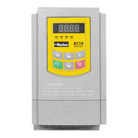
Parker AC10 series Product Manual (151 pages)
AC10 Series, IP20 0-180kW
Brand: Parker
|
Category: Inverter Drive
|
Size: 5.44 MB
Table of Contents
-
-
Connection27
-
-
-
-
-
General101
-
Modbus Protocol101
-
Baud Rate F904101
-
Frame Structure102
-
Error Check102
-
ASCII Mode102
-
RTU Mode102
-
-
-
Examples109
-
-
-
-
-
EMC Directive123
-
EMC Compliance123
-
-
Radiated124
-
-
-
UL Standards126
-

Parker AC10 series Product Manual (151 pages)
Brand: Parker
|
Category: Inverter Drive
|
Size: 4.06 MB
Table of Contents
-
-
The Display20
-
Installation25
-
Connection27
-
Grounding38
-
Control Mode41
-
-
-
-
General101
-
Modbus Protocol101
-
Baud Rate F904101
-
Frame Structure102
-
Error Check102
-
ASCII Mode102
-
RTU Mode102
-
Control Commands105
-
Examples109
-
-
-
EMC Directive123
-
EMC Compliance123
-
Radiated124
-
UL Standards126

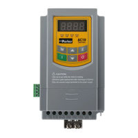
Parker AC10 series Product Manual (145 pages)
AC Variable Frequency Drives, IP66 0 - 15kW
Brand: Parker
|
Category: Controller
|
Size: 5.15 MB
Table of Contents
-
-
Storage17
-
-
Installation23
-
Connection23
-
-
-
-
-
General97
-
-
ASCII Mode97
-
RTU Mode97
-
Baud Rate97
-
Error Check98
-
ASCII Mode98
-
RTU Mode98
-
-
-
Examples106
-
-
-
-
-
EMC Directive120
-
EMC Compliance121
-
-
-
Radiated122
-
Fuse Ratings123
-
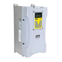
Parker AC10 series Quick Start Manual (61 pages)
IP20 0.25 - 250 HP (0.2 - 180 kW). IP66 0.5 - 125 HP (0.4 - 90 kW
Brand: Parker
|
Category: Controller
|
Size: 4.94 MB
Table of Contents
-
Hazards4
-
Emc5
-
-
Compliance29