beautypg.com
Manuals
Brands
Parker Manuals
DC Drives
LINKnet AC30D
Parker LINKnet AC30D Manuals
Manuals and User Guides for Parker LINKnet AC30D. We have
5
Parker LINKnet AC30D manuals available for free PDF download: Hardware Installation Manual, User's Product Manual, Product Manual, Safety & Quickstart Booklet
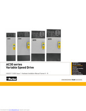
Parker LINKnet AC30D Hardware Installation Manual (176 pages)
Variable Speed Drive
Brand:
Parker
| Category:
Inverter
| Size: 9.97 MB
Table of Contents
Table of Contents
5
Chapter 1: Safety
9
Requirements
9
Intended Users
9
Application Area
9
Personnel
10
Hazards
10
Chapter 2: Introduction
13
About this Manual
13
Packaging and Lifting Details
15
Chapter 3: Product Overview
17
Product Range
17
Power Stack Features
18
Power Stack Functional Overview
19
AC30 Series Control Features
21
Chapter 4 : Installation - Power Stack
23
Cubicle Mount Power Stack
23
Dimensions for Cubicle Mount Installation
23
Mounting the Inverter
24
Ventilation
24
Power Stack Electrical Installation
25
Wiring Instructions
25
Terminal Cover Removal
26
AC Line Fed Power Stack Wiring Connections
27
DC Link FED Power Stack Wiring Connections
28
Dynamic Brake Resistor Wiring Connections (Frame K Only)
30
Power Stack Terminal Block Wire Range
31
Power Stack Terminal Tightening Torques
33
Front Panel Removal
34
AC Line Fed Power Stack - Fan Supply Voltage Selection
35
DC Link Fed Power Stack - Fan Supply Voltage Selection
36
AC Line Fed Power Stack - Y-Cap & VDR Disconnects
37
DC Link Fed Power Stack - Y-Cap Disconnect
38
Chapter 5: Installation - Control Module
39
Control Module
39
Product Dimensions
39
Control Module Electrical Installation
40
Wiring Instructions
40
Control Module Cover Removal
41
Control Module Removal
42
AC30V Control Wiring Connections
43
AC30P & AC30D - Control Wiring Connections
44
System Board Control Wiring Connections (AC30D ONLY)
45
Wiring Diagrams
46
The Default Application
46
Application Description
46
Application 0: Basic Speed Control
48
Application 1: Auto/Manual Control
50
Application 2
52
Raise / Lower Trim
52
Application 3: Presets Speeds
54
Application 4: PID Control
56
Application 5: Active Front-End
58
Control Module Terminal Block Wire Range
60
Control Module Terminal Block Cable & Ferrule Recommendations
60
Control Module Cabling Bracket (Optional)
61
Ethernet Communications Cable
62
Ethernet Cable Recommendation
63
OPTION & Communication CARD Installation Details (Optional)
64
SD CARD Installation
66
Fitting a Remote GKP
67
Chapter 6: Associated Equipment - Power Stack
69
AC Line Fed 710 Stacks: Connection Overview
69
AC Line Input Fuses
70
Circuit Breakers (Alternative to AC Line Fuses)
71
External EMC Filters (Optional)
71
AC Line Chokes (Optional)
72
Dynamic Braking Resistors (Optional)
73
AC Motor Chokes (Optional)
74
DC Link Fed 740 Stacks: Connection Overview
75
AC Line Input Fuses
76
External EMC Filters (Optional)
76
AC Line Choke
76
Pre-Charge Considerations
76
DC Link Input Fuses
78
AC Motor Chokes (Optional)
78
AFE System Using DC Link Fed 740 Stacks: Connection Overview
79
AC Line Input Fuses
80
External EMC Filters (Optional)
80
DC Link Input Fuses
80
AC Motor Chokes
80
Line Synchronisation Card & AC30 Control Module
81
Chapter 7: Associated Equipment - Control Module
83
Cabling Brackets
83
Option Cards
83
Communication Cards
84
SD Memory Cards
84
Graphical Keypad (GKP)
85
Chapter 8: Safe Torque off Sil3/Ple
87
General Information
87
STO Functional Description
88
Alignment to European Standards
89
En Iso13849-1:2008
89
EN61800-5-2:2007 and EN61508
90
Safety Specification
91
EMC Specification
92
User Connections
93
STO Technical Specification
95
Inputs Specification
95
Output Specification
95
Truth Table
96
STO Input Timing Diagrams
97
Ideal Operation
97
Typical Operation
98
Fault Operation
99
Pulsed Inputs
100
STO State Transition Diagram
101
STO Trip Annunciation
102
Safety Warnings and Limitations
103
Example User Wiring
105
Applications that Do Not Require STO Function
105
Minimum STO Implementation
106
STO Implementation with Safety Control Unit
107
SS1 Implementation Using Safety Control Unit
109
STO Function Checking
111
Comprehensive Check
112
The Following Test Steps Must be Performed
113
Regular Check
115
Troubleshooting
116
Chapter 9: The Graphical Keypad
117
Overview
117
Keypad
118
LED Status Indication
119
The Display
120
Top Line - Inverter Status Summary
120
Bottom Line - Soft Key Action Indication
121
Setup Wizard
122
Firmware Update
123
Chapter 10: Routine Maintenance & Repair
125
Routine Maintenance
125
Preventative Maintenance
125
Main Duct Fans
125
DC Link Capacitors
125
Repair
125
Saving Your Application Data
125
Returning the Unit to Parker
125
Appendix A: Compliance
127
Applicable Standards
127
European Compliance
128
CE Marking
128
EMC Compliance
130
EMC Standards
131
Radiated Emissions Standards
131
Conducted Emissions Standards
132
Radiated & Conducted Emissions - Compliance Overview
133
EMC Installation Guidance
135
Protective Earth (PE) Connections
135
Mitigating Radiated Emissions
137
Cabling Requirements
139
Harmonic Information - AC Supplied Inverters
143
Requirements for North American and Canadian Compliance
147
North American Compliance
147
Canadian Compliance
148
North American and Canadian Compliance Information
148
Environmental
150
Restriction, Evaluation, Authorisation and Restriction of Chemicals (REACH
150
Restriction of Hazardous Substances (Rohs
150
Waste Electrical and Electronic Equipment (WEEE
151
Appendix B: E Plan Library
153
E Plan Library
154
Appendix D: AC30 Series Product Codes
155
Understanding the Product Code
155
AC30 Series Control Module
155
AC30 Series Power Stack
156
Configured AC30 Series Inverter
157
AC30 Series Regenerative Supply Unit
158
Appendix E: Technical Specifications - Power Stack
159
Environmental Details
159
Safety Details
160
Earthing Details
160
Cooling Fans
161
AC FED Electrical Ratings
162
DC FED Electrical Ratings
164
AFE Mode Electrical Ratings
165
Internal Dynamic Brake Switch
165
Appendix F: Technical Specifications - Control Modulef-1
167
Environmental Details
167
Safety Details
168
Analog Inputs/Outputs
168
Reference Outputs
169
Digital Inputs
169
Digital Outputs
169
User 24V Supply OUTPUT
170
Auxiliary 24V Input (AC30V & Ac30P Only
170
Relays (AC30V ONLY
170
SYSTEM Auxiliary 24V Input (AC30D ONLY
171
DIGITAL Inputs (AC30D ONLY
171
Encoder Power Supply Output (AC30D ONLY
172
Encoder Inputs (AC30D ONLY
173
Encoder Transmit Outputs (AC30D ONLY
174
Parker LINKnet AC30D User's Product Manual (161 pages)
AC30 series Variable Speed Drive
Brand:
Parker
| Category:
DC Drives
| Size: 5.6 MB
Table of Contents
Table of Contents
4
Chapter 1: Safety
9
Chapter 11: Routine Maintenance & Repair
10
Chapter 2: Introduction
13
About this Manual
13
Chapter 12: Ethernet
14
Packaging and Lifting Details
15
Chapter 3: Product Overview
16
Product Range
16
Control Features
17
Functional Overview
18
Chapter 4: Installation
21
Dimensions for Cubicle Mount Installation - Frame K
22
Mounting the Inverter
23
Ventilation
23
Cubicle Mounting Details
24
Cubicle Mount
21
Dimensions for Cubicle Mount Installation
21
Through Panel Mount Frames D to J Only
25
Dimensions for through Panel Installation
25
Frames D, E
25
Frames F, G
26
Frame H
27
Frame J
28
Mounting the INVERTER
29
Ventilation
29
Through Panel Mounting Detail (Frames D - J Only)
30
Cover Removal Instructions - All Frames
30
Cabling Bracket for Control & Main Cable
33
Cabling Bracket for AC30D System Terminals
34
Appendix C: Compliance
35
AC Fed Power Wiring Connections
36
DC FED Power Wiring Connections (Frames D - J Only)
37
Electrical Installation
35
Wiring Instructions
35
Control Module Cover Removal
38
Control Module Removal
39
Control Module Terminal Cable Specification
40
AC30V Control Wiring Connections
41
AC30D-P Control Wiring Connections
42
System Board Control Wiring Connections - AC30D ONLY
43
Wiring Diagrams
44
The Default Application
44
Application Description
44
Application 0: Basic Speed Control
46
Application 1: Auto/Manual Control
48
Application 2: Raise / Lower Trim
50
Application 3: Presets Speeds
52
Application 4: PID Control
54
Application 5: Active Front-End
56
Terminal Block Wire Range
58
Terminal Tightening Torques
59
Optional Equipment
59
Brake Wiring
59
Fitting a Remote GKP
60
Getting Started
61
GKP Setup Wizard
61
Ethernet Communications
62
Recommended Cable
62
Firmware Update
65
Updating the Inverter Firmware
65
Chapter 5: Associated Equipment
66
Main Points
66
AC Motor Chokes
69
Dynamic Braking Resistors
70
Wiring Details
70
Dynamic Braking Resistors
71
Resistor Selection
71
Circuit Breakers
73
External EMC Filters
73
Input Chokes
74
Gasket Kits
74
Cabling Bracket for Control, System Option & Power Stack
74
Option Cards
75
SD Cards
75
Installation Details
76
Repair
78
STO Functional Description
79
Configuration
79
Chapter 6 Safe Torque off Sil3/Ple
78
General Information
78
Alignment to European Standards
80
En Iso13849-1:2008
80
EN61800-5-2:2007 and EN61508
81
Safety Specification
82
Radiated
83
EMC Specification
83
User Connections
84
STO Technical Specification
86
Inputs Specification
86
Output Specification
87
Truth Table
88
STO Input Timing Diagrams
89
Ideal Operation
89
Typical Operation
90
Fault Operation
91
Pulsed Inputs
92
Appendix B: Sequencing Logic
93
State Transitions
93
Chapter 13 : Fire Mode
93
STO State Transition Diagram
93
STO Trip Annunciation
94
Safety Warnings and Limitations
95
Example User Wiring
97
Applications that Do Not Require STO Function
97
Minimum STO Implementation
98
STO Implementation with Safety Control Unit
99
SS1 Implementation Using Safety Control Unit
101
STO Function Checking
103
Comprehensive Check
104
The Following Test Steps Must be Performed
105
Regular Check
109
Troubleshooting
110
Chapter 7: The Graphical Keypad
112
Overview
113
Keypad
114
The Display
115
Inverter Status Summary
115
Soft Key Action Indication
116
Leds
117
The Menu System
118
Navigating the Menu System
118
Changing a Parameter Value
118
Trips and Other Information Displays
119
Setting the Display Language
119
Setting the Display Language to Custom
119
Chapter 8: Menu Organisation
120
Menu Map
120
Menu Map Summary
120
Web Pages
120
Menu Descriptions
121
Control Screen
121
Setup
121
Monitor
121
Favourites
121
Parameters
121
Configuration
121
Parameter Map
122
Peer to Peer
124
Chapter 9: Setup Wizard
126
GKP Setup Wizard
126
Configuration
126
Devicenet Option
132
Encoder
134
Set up PMAC Motor Control - Sensorless
134
Encoder Slot 1
135
Set up PMAC Motor Control - Encoder Feedback
135
Set up PMAC Motor Control - Pos Alignment after Power-Up
137
Parker Drive Quicktool (PDQ) PC Software
138
Installation
138
Starting the Wizard
140
Task Selection
141
Find Drive
142
Ethernet
142
Select Macro
144
Setup I/O
145
Select Motor
146
Setup the Drive Control
149
Setup Communications
150
Commission the Drive
151
Monitor the Drive
152
Chapter 10: Trips & Fault Finding
154
Trips and Fault Finding
154
What Happens When a Trip Occurs
154
Resetting a Trip Condition
154
Control Word
154
Using the Keypad to Manage Trips
155
Feedbacks
157
Appendix D: Parameter Reference
158
Control Mode
158
Hexadecimal Representation of Trips
160
Fault Finding
160
Parker LINKnet AC30D Product Manual (82 pages)
Brand:
Parker
| Category:
DC Drives
| Size: 2.62 MB
Table of Contents
Table of Contents
3
Chapter 1 English
5
Safety Information
5
Quickstart
7
Before You Start
7
About this Quickstart
7
Overview
8
Control Module Cover Removal
9
Control Module Removal
9
Top & Bottom Cover Removal Instructions
10
Top Cover Removal
10
Bottom Cover Removal
10
Cabling Bracket for Control & Main Cable
11
Power Wiring Connections
11
Dynamic Braking Resistors
12
Internal Filter Disconnection
12
Power Ratings
12
Drive Start-Up
13
Drive Setup
13
Motor Data
13
Getting Started - GKP Setup Wizard
14
Purpose of the Setup Wizard
14
Starting the Setup Wizard
14
Running the Setup Wizard
14
Setup Wizard Stages
14
Finalising Setup
14
Ethernet Communications
14
Compliance
15
Chapter 2 Deutsch
16
Sicherheits Informationen
16
Schnellstartanleitung
18
Erste Schritte
18
Zu dieser Schnellstartanleitung
18
Übersicht
19
Entfernen der Steuermodulabdeckung
20
Schaltpläne
20
Entfernen des Steuermoduls
20
Entfernen der Oberen und Unteren Abdeckung
21
Entfernen Sie Obere Abdeckung
21
Entfernen der Unteren Abdeckung
21
Kabelhalterung für Steuerungs- und Hauptkabel
22
Stromanschlüsse
22
Dynamische Bremswiderstände
23
Trennen des Internen Filters
23
Leistungsdaten
23
Inbetriebnahme des Antriebs
24
Konfiguration des Antriebs
24
Motordaten
24
Erste Schritte - GKP-Setup-Assistent
25
Zweck des Setup-Assistenten
25
Starten des Setup-Assistenten
25
Ausführen des Setup-Assistenten
25
Arbeitsschritte IM Setup-Assistenten
25
Abschließen der Konfiguration
25
Ethernetverbindungen
25
Konformität
26
Chapter 3 Français
27
Informations de Sécurité
27
Risques
27
Démarrage Rapide
29
Avant de Démarrer
29
À Propos de Ce Guide de Demarrage Rapide
29
Présentation
30
Retrait de la Protection du Module de Commande
31
Schémas de Câblage
31
Retrait du Module de Commande
31
Retrait des Protections Supérieure et Inférieure
32
Top Dépose du Couvercle
32
Retrait de la Protection Inférieure
32
Support de Câblage pour le Câble Principal et le Câble de Commande
33
Raccordements D'alimentation
33
Résistances de Freinage Dynamique
34
Déconnexion du Filtre Interne
34
Puissance
34
Démarrage du Variateur
35
Réglage du Variateur
35
Données du Moteur
35
Démarrage - Assistant de Réglage GKP
36
Objectif de L'assistant de Réglage
36
Démarrage de L'assistant de Réglage
36
Exécution de L'assistant de Réglage
36
Étapes de L'assistant de Réglage
36
Finalisation du Réglage
36
Communications Ethernet
36
Conformité
37
Chapter 4 Italiano
38
Informazioni Sulla Sicurezza
38
Guida Rapida
40
Prima DI Iniziare
40
Informazioni Su Questa Guida Rapida
40
Panoramica
41
Rimozione Coperchio Modulo DI Comando
42
Schemi DI Cablaggio
42
Rimozione del Modulo DI Comando
42
Rimozione Coperchio Superiore E Inferiore
43
Rimozione Top Cover
43
Rimozione Coperchio Inferiore
43
Staffa DI Cablaggio Per Cavi DI Comando E Alimentazione
44
Collegamenti Elettrici
44
Resistenze DI Frenatura Dinamica
45
Scollegamento del Filtro Interno
45
Valori DI Potenza Nominale
45
Messa in Funzione Dell'inverter
46
Configurazione Dell'inverter
46
Dati Motore
46
Come Iniziare - Procedura Guidata DI Configurazione Tramite Tastiera Grafica (GKP)
47
Scopo Della Procedura Guidata DI Configurazione
47
Avvio Della Procedura Guidata DI Configurazione
47
Esecuzione Della Procedura Guidata DI Configurazione
47
Fasi Della Procedura Guidata DI Configurazione
47
Completamento Della Configurazione
47
Comunicazioni Ethernet
47
Conformità
48
Chapter 5 Polski
49
Informacje Dotyczące Bezpieczeństwa
49
Instrukcja Szybkiego Uruchomienia
51
Przed Rozpoczęciem
51
O Niniejszej Instrukcji Szybkiego Uruchomienia
51
Widok Ogólny
52
Demontaż Pokrywy Modułu Sterowania
53
Demontaż Modułu Sterowania
53
Instrukcje Demontażu Pokrywy Górnej I Dolnej
54
Demontaż Pokrywy Górnej
54
Demontaż Pokrywy Dolnej
54
Płytka Do Mocowania Okablowania Sterowniczego I Zasilania
55
Podłączenie Przewodów Zasilających
55
Rezystory Hamowania Dynamicznego
56
Odłączanie Wewnętrznego Filtra
56
Parametry Znamionowe
56
Uruchomienie Przemiennika
57
Konfiguracja Przemiennika
57
Parametry Silnika
57
Pierwsze Kroki - Kreator Konfiguracji Modułu GKP
58
Przeznaczenie Kreatora Konfiguracji
58
Uruchamianie Kreatora Konfiguracji
58
Praca Z Kreatorem Konfiguracji
58
Etapy Kreatora Konfiguracji
58
Zakończenie Konfiguracji
58
Komunikacja Ethernet
58
Kompatybilność
59
Chapter 6 Español
60
Información de Seguridad
60
Inicio Rápido
62
Antes de Comenzar
62
Acerca de Este Manual de Inicio Rapido
62
Descripción General
63
Extracción de la Cubierta del Módulo de Control
64
Diagramas del Cableado
64
Extracción del Módulo de Control
64
Extracción de las Cubiertas Superior E Inferior
65
Extracción de la Cubierta Inferior
65
Soporte del Cableado para el Cable de Control y el Principal
66
Conexiones del Cableado de Alimentación
66
Resistencias de Frenado Dinámico
67
Desconexión del Filtro Interno
67
Índices de Energía
67
Puesta en Marcha de la Unidad
68
Configuración de la Unidad
68
Datos del Motor
68
Objetivo del Asistente de Configuración
69
Inicio del Asistente de Configuración
69
Ejecución del Asistente de Configuración
69
Fases del Asistente de Configuración
69
Finalización de la Configuración
69
Comunicaciones Ethernet
69
Cumplimiento
70
Chapter 7 Svenska
71
Säkerhetsinformation
71
Snabbstart
73
Innan du Startar
73
Om Denna Snabbstart
73
Översikt
74
Ta Bort Kontrollmodulens Hölje
75
Ta Bort Kontrollmodulen
75
Instruktioner För Att Ta Bort Det Övre Och Nedre Höljet
76
Ta Bort Det Övre Höljet
76
Ta Bort Det Nedre Höljet
76
Kabelfäste För Signalmotor & Matningskabel
77
Anslutningar Med Strömkablage
77
Resistorer För Dynamisk Broms
78
Bortkoppling Av Internt Filter
78
Effektklassningar
78
Starta Enheten
79
Inställningar Av Enheten
79
Motordata
79
Komma Igång-Installationsguide För Operatörspanelen
80
Syftet Med Installationsguiden
80
Starta Installationsguiden
80
Köra Installationsguiden
80
Delar Av Installationsguiden
80
Avsluta Installationen
80
Ethernet-Kommunikation
80
Chapter 8 Dimensions for Panel Mount Installations
81
Abmessungen für Plattenmontage-Installation
81
Dimensions pour L'installation du Panneau Monté
81
Dimensioni Per L'installazione Su Pannello
81
Wymiary Do Montażu Wpuszczanego W Panelu Montażowym
81
Dimensiones para la Instalación en el Montaje en el Panel
81
Dimensioner VID Installation För Montering Genom Panel
81
Chapter 9 Applications
82
Application 0: Basic Speed Control (Default)
82
Parker LINKnet AC30D Product Manual (56 pages)
Brand:
Parker
| Category:
DC Drives
| Size: 3.48 MB
Table of Contents
Contents
3
Table of Contents
3
Chapter 1 - Overview
5
Further Reading
6
Product Features
6
Ethernet Protocols Supported
6
Software Requirements
6
Hardware Supported
6
Restrictions
6
Ethernet Recommendations
7
Web Page
7
Communication Differences
7
Chapter 2 - Installation
8
Wiring Requirements
8
Getting Started - Updating the Drive Firmware
9
Updating Codesys Firmware to Linknet Firmware Using DSE
9
Updating a Linknet Drive to Linknet Using DSE
11
The Drive Already Has Linknet Firmware Installed
11
Updating the Drive Firmware Using a SD Card
13
Getting Started - GKP (Graphical Key Pad)
14
Getting Started - Connecting to DSE
14
Chapter 3 - Initial Set-Up
16
IP Addressing Information
16
Setting the Node Address
17
Setting the Computer IP Address for AC30 Linknet Access Via Ethernet
18
Chapter 4 - Using DSE and AC30 Programming
20
Node Addressing the Linknet Modules
20
Watchdog Circuit
24
Saving of Drive Parameters
24
Saving of Favorites in the GKP
25
Parameter Color Definition
25
Duplicate Node Address
26
Duplicate IP Address
26
Active Ethernet Connection
26
AC30 Additional Function Blocks
27
AC30P/D Phase Blocks
28
Chapter 5 - Connecting to the Drive
29
Command / Get Info
30
Chapter 7 - AB Ethernet /IP Server (Slave) Example
31
Chapter 8 - Ethernet Network Topology & EDS File
34
EDS File
34
Chapter 9 - Programming TS8000
35
Required Modbus Settings
35
Example: Configuring a TS8000 to Communicate to a AC30V
37
Step 1: Configuring the Modbus Slave Option Using DSE
37
Chapter 10 - Using Remote I/O
45
Setting up Internal Watchdog on Wago I/O Coupler, 750-352
47
Chapter 11 - Troubleshooting
50
Duplicate Node Address
50
Duplicate IP Address
50
Active Ethernet Connection
50
Chapter 12 Technical Specifications & Performance
51
Chapter 13 Recommended Auxiliary Products
52
Remote IO
52
Unmanaged Ethernet Switches
52
Other Communication Networks
52
Appendix A - AC30 Firmware Release Notes
53
Parker LINKnet AC30D Safety & Quickstart Booklet (28 pages)
Brand:
Parker
| Category:
DC Drives
| Size: 0.79 MB
Table of Contents
Table of Contents
3
Chapter 1: English
5
Safety Information
5
Quickstart
7
Before You Start
7
About this Quickstart
7
Overview
8
Dimensions for Panel Mount Installation
9
Top & Bottom Cover Removal
9
Cabling Bracket for Control & Main Cable
10
Power Wiring Connections
10
Control Module Cover Removal
11
Minimum Wiring Diagram - Minimum Connections
12
Minimum Wiring Diagram - Basic Speed Control
13
Minimum Wiring Diagram - Presets
13
Minimum Wiring Diagram - Raise / Lower
14
Minimum Wiring Diagram - PID
14
Dynamic Braking Resistors
15
Frame Ratings
15
Drive Start-Up
16
Drive Setup
16
Motor Data
16
Getting Started - GKP Setup Wizard
17
Purpose of the Setup Wizard
17
Starting the Setup Wizard
17
Running the Setup Wizard
17
Finalising Setup
17
Ethernet Communications
17
Compliance
18
Chapter 2: Deutsch
19
Sicherheits Informationen
19
Chapter 3: Français
22
Informations de Sécurité
22
Risques
22
Chapter 4: Italiano
24
Informazioni Sulla Sicurezza
24
Chapter 5: 中文
26
Related Products
Parker ac890
Parker LINKnet AC30P
Parker AC20 Series
Parker AC15 Series
Parker AC70
Parker AC20F Series
Parker Compumotor AX57-83
Parker Compumotor AX57-102
Parker Compumotor AX83-62
Parker Compumotor AX106-178
Parker Categories
Controller
Control Unit
Industrial Equipment
Dryer
DC Drives
More Parker Manuals