Raisecom Gazelle S1000i2GF-8GE-PWRLI Manuals
Manuals and User Guides for Raisecom Gazelle S1000i2GF-8GE-PWRLI. We have 1 Raisecom Gazelle S1000i2GF-8GE-PWRLI manual available for free PDF download: User Manual
Raisecom Gazelle S1000i2GF-8GE-PWRLI User Manual (94 pages)
Table of Contents
-
1 Overview
13 -
-
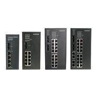
Appearance17
-
Interfaces28
-
-
Button34
-
Leds34
-
Power Supply36
-
Cables38
-
Ground Cable38
-
Fiber46
-
-
-
-
-
-
-
Ping78
-
Traceroute79
-
System Log79
-
Watchdog79
-
-
7 Appendix
82
Related Products
- Raisecom Gazelle S1000i2GF-4FE-LI
- Raisecom Gazelle S1000i2GF-8FE-LI
- Raisecom Gazelle S1000i2GF-4GE-LI
- Raisecom Gazelle S1000i2GF-8GE-LI
- Raisecom Gazelle S1000i-LI
- Raisecom Gazelle S1000i4GF-16FE-LI
- Raisecom Gazelle S1000i4GX-16FE-LI
- Raisecom Gazelle S1020i2GF-4GE-GLDCW48
- Raisecom Gazelle S1020i4GF-8GE-GLAC
- Raisecom Gazelle S1020i-LI