beautypg.com
Manuals
Brands
S&T Manuals
Motherboard
44011-0208-15-2
S&T 44011-0208-15-2 Manuals
Manuals and User Guides for S&T 44011-0208-15-2. We have
1
S&T 44011-0208-15-2 manual available for free PDF download: User Manual
S&T 44011-0208-15-2 User Manual (65 pages)
Brand:
S&T
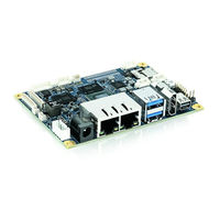
| Category:
Motherboard
| Size: 4.67 MB
Table of Contents
Symbols
6
For Your Safety
7
High Voltage Safety Instructions
7
Special Handling and Unpacking Instruction
7
Lithium Battery Precautions
8
General Instructions on Usage
8
Quality and Environmental Management
8
Disposal and Recycling
8
WEEE Compliance
8
Table of Contents
9
List of Tables
10
List of Figures
11
1/ Introduction
13
2/ Description
14
Configurations
15
Table 1: Component Main Data
15
Scope of Delivery
16
Table 2: Scope of Delivery Pitx-Imx8M
16
Table 3: Scope of Pitx-Imx8M Kit
16
Figure 1: Pitx-Imx8M Board
16
3/ Installation Procedure
17
Installing the Board
17
Safety Requirements According IEC 62368
18
Figure 2: Power Jack (Left) and Internal Connector(Right)
18
Lithium Battery Precautions
19
4/ System Specifications
20
Component Main Data
20
Table 4: Component Main Data
20
Environmental Conditions
22
Table 5: Environmental Conditions
22
Block Diagram
23
Figure 3: Block Diagram
23
Power Consumption
25
Table 6: Power Consumption
25
5/ Jumpers, Switches and Connectors
26
Hardware Configuration Setting
26
Table 7: Jumpers and Connectors
26
Table 8: Switch SW1
27
Table 9: Switch SW2
27
Mainboard Placement and I/O Locations
28
Figure 4: Front Side
28
Figure 5: Interfaces
29
Figure 6: Front View Jumpers/Switches
30
Interfaces Rear Side
31
Figure 7: Interfaces Rear Side
31
Cooler Solutions
32
Passive Cooler (1064-7069)
32
Active Cooler (1064-8396)
32
Figure 8: Passive Cooler
32
Figure 9: Active Cooler
32
6/ Hardware Specifications
33
Processor Support
33
Table 10: Processor Support
33
System Memory Support
34
Figure 10: Block Diagram I.mx8M Processor (Source: NXP)
34
Microsd and Microsim (J12)
35
Table 11: Pin Assignment Microsim Combo Socket
35
Figure 11: Combo Connector for Microsd and Microsim
35
Ethernet Connectors (I/O Area, J4)
36
Table 12: Pin Assignment Dual Ethernet
36
Figure 12: Ethernet Connector RJ-45 Jack with Integrated Magnetic
36
ETH0 Leds
37
ETH1 Leds
37
USB Connectors
37
USB Connectors (I/O Area, J13)
37
Table 13: ETH0 LED Signal Description
37
Table 14: ETH1 LED Signal Description
37
Table 15: Pin Assignment Dual USB
37
Figure 13: USB 2.0/3.0 Socket
37
Table 16: Signal Description
38
Table 20: Signal Description
38
USB Internal (J2)
39
Usb Otg (J28)
39
Table 17: USB Internal Connection
39
Table 18: USB OTG Connection
39
Figure 14: USB Internal Connector
39
Figure 15: USB OTG Connector
39
Fan Connector (Internal, J8)
40
DC Power Supply Connector Options
40
Table 19: Fan Header Mapping
40
Figure 16: 3-Pin Fan Connector
40
DC Power Jack Connector (12 Vin Ext., J15)
41
Internal Power Connector (Vin Int., J16)
41
Table 21: Power Jack Connector
41
Table 22: Internal Power Connector
41
Figure 17: Power Jack Connector
41
Figure 18: Internal Power Connector
41
Pigtail Battery Header (J22)
42
GPIO Connector (Internal, J17)
42
Table 23: Pin Assignment
42
Table 24: GPIO Connector
42
Figure 19: Pigtail Battery Header
42
Figure 20: GPIO Connector
42
Jumper LVDS Panel Voltage (J18)
43
Jumper LVDS Backlight Voltage (J29)
43
Table 25: LVDS Panel Voltage
43
Table 26: LVDS Panel Voltage
43
Figure 21: LVDS Panel Voltage
43
Figure 22: LVDS Backlight Voltage Select Jumper
43
Switches
44
Boot Select (SW1)
44
Microsd Card Write Protection (SW2)
44
PCIE Spread Spectrum Clocking -0.5% (SW2: 2-3)
44
Buttons
44
External ON-OFF Button (J24)
44
Table 27: Boot Select Switch (SW1)
44
Table 28: Microsd Card Write Protection Switch
44
Table 29: PCIE Spread Spectrum Clocking -0.5% Switch
44
Table 30: External ON-OFF Button
44
External Reset (J23)
45
LVDS (Industrial Variant, Internal, J11)
45
Table 31: External Reset Button
45
Table 32: LVDS Pin Assignment
45
Figure 23: LVDS Connector (Optional)
45
HDMI Connector (J7)
46
Table 33: HDMI Mapping
46
Figure 24: 19-Pin HDMI Connector
46
Mini Display Port (J14)
47
Table 34: Mini Display Port
47
Figure 25: Mini Display Port
47
SPDIF Internal Audio Header (J10)
48
Table 35: Pin Assignment
48
Figure 26: SPDIF Internal Header with 3 Pins
48
Internal Audio (J9)
49
Spi/I2C3 (J26)
49
Table 36: Pin Assignment
49
Table 37: SPI/I2C Pin Assignment
49
Figure 27: Internal Audio Header with 6 Pins
49
Connector (B-Key) (J1)
50
Table 38: Pin Assignment
50
Figure 28: M.2 Connector (B-Key)
50
Serial COM P1 (J25)
52
Serial COM P2 (J3)
52
Table 39: Pin Assignment
52
Table 40: Pin Assignment
52
Figure 29: Serial Wafer Socket COM P1
52
Figure 30: Serial Wafer Socket COM P2
52
Serial COM P3 (J19)
53
Camera Connector (J5, J6)
53
Table 41: Pin Assignment (Assembly Option)
53
Table 42: Pin Assignment RS232 Only
53
Table 43: Pin Assignment (J5)
53
Figure 31: Serial Wafer Socket COM P3
53
Figure 32: 24-Pin Camera CSI Connector
53
Table 44: Pin Assignment (J6)
55
Thermal Sensor (U24)
56
Figure 33: Sensor Location (Red Circle)
56
7/ Bootloader Operation
57
Copyrights and Licensing of U-Boot
57
Bootloader Quickstart
57
Bootloader Commands
58
Figure 34: U-Boot Start Screen
58
Kontron Bootloader Command Extensions
59
Kboardinfo - Kontron Board Information
59
Bootloader Environment
59
Table 45: Bootloader Command Extensions
59
Figure 35: Kboardinfo
59
Bootloader Environment Update
60
Table 46: Standard Environment Variables
60
Kontron Bootloader Environment Extensions
61
Bootloader Mass Storage Support
61
QSPI Flash
61
Table 47: Bootloader Environment Extensions
61
SD Card and Emmc Devices
62
USB Storage Device
62
Bootloader File System Support
62
Bootloader Update
62
8/ Technical Support
63
Warranty
63
Returning Defective Merchandise
63
About Kontron - Member of the S&T Group
65
Related Products
S&T 44011-0408-13-4
S&T 44011-0408-15-4
S&T 44011-0208-13-2
S&T 40099 227
S&T 40099 229
S&T 40099 231
S&T Kontron Mini ITX Skylake S/C236
S&T Kontron mITX-KBL-S-C236
S&T Kontron pITX-iMX8M
S&T Kontron QDS-6100
S&T Categories
Computer Hardware
Switch
Desktop
Motherboard
GPS
More S&T Manuals