beautypg.com
Manuals
Brands
S&T Manuals
Industrial PC
KBOX C-103-NGSF
S&T KBOX C-103-NGSF Manuals
Manuals and User Guides for S&T KBOX C-103-NGSF. We have
1
S&T KBOX C-103-NGSF manual available for free PDF download: User Manual
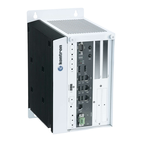
S&T KBOX C-103-NGSF User Manual (90 pages)
Brand:
S&T
| Category:
Industrial PC
| Size: 5.08 MB
Table of Contents
Symbols
6
For Your Safety
8
High Voltage Safety Instructions
8
Lithium Battery Precautions
9
General Instructions on Usage
9
Quality and Environmental Management
9
Disposal and Recycling
9
WEEE Compliance
9
Table of Contents
11
List of Tables
14
List of Figures
14
1 / General Safety Instructions
16
Electrostatic Discharge (ESD)
19
Grounding Methods
19
Instructions for the Optional Lithium Battery
19
2 / Shipment and Unpacking
20
Unpacking
20
Scope of Delivery
20
Optional Parts (System Expansion)
20
Optional System Extension
20
Type Label and Product Identification
20
Table 2: Product Identification Table
21
Figure 1: Example of Kbox C-103-NGSF Type Label
21
3 / System Overview
22
Optional RTC Lithium Battery (Internally-Accessible)
23
System Expansion Capabilities
23
Interfaces
23
Mini PCI Express Interface
23
Standard PCI Express Interfaces
23
SATA Interfaces
23
Internal USB 3.0 Interface
24
Internal Microsd Card and Microsim Card Interface
24
Figure 4: Bottom Side View
25
Figure 5: Right Side View
25
Figure 6: Front Side View Config. with Removable Drives
25
Figure 7: Front Side View Config. Without Removable Drives
25
Figure 8: Left Side View
25
Figure 9: Top Side View
25
Figure 10: Rear Side View
25
Kbox C-103-NGSF Variant
26
Figure 11: Kbox C-103-NGSF - Front View (Shown with Removable Drive Bays and Without Mounting Brackets)
26
Figure 12: Block Diagram - Kbox C-103-NGSF
27
X101/X201 - Power Input Connectors
28
X102/X105/X108/X111 - Ethernet Connectors (ETH)
29
X103/X106/X109 - Usb 3.0
29
X104/X107/X110 - Usb 2.0
29
Figure 14: X101 - 24VDC Power Input Connector
29
X112/X113/X203 - Displayports
30
X114 - RS232 Port
30
POWER Button and PWR LED
30
Figure 12: Detail - Power Button and PWR Led/Rescue Button and RSQ LED
30
RESCUE Button and RSQ LED
31
Status and General Purpose Leds
31
Table 4: Status and General Purpose Leds
31
Figure 16: Detail - Status and General Purpose Leds
31
Pci/Pcie Expansion Slots
32
Internal or Removable 2.5" SATA Hdds/Ssds
33
Figure 14: Drive 1 and Drive 2 for Removable 2.5" SATA HDD/SSD (Option); Closed Drive Bays
33
Figure 15: Drive Bay 1 with Opened Drive Bay Cover
33
Figure 16: Inserting/Removing a 2.5" Removable SSD
33
Installing/Removing the Removable HDD/SSD
34
Left and Right Side View
35
Top and Bottom Side View
35
Figure 17: Right Side of the Kbox C-103-NGSF System
35
Figure 18: Left Side of the Kbox C-103-NGSF System
35
Figure 19: Top Side of the Kbox C-103-NGSF System
35
Figure 20: Bottom Side of the Kbox C-103-NGSF System
35
Rear Side View
36
Functional Earth Stud
36
Figure 21: Rear Side of the Kbox C-103-NGSF System
36
4 / System Extensions
38
X203)
38
Rd Displayport
38
X206) Wifi
38
Wifi/Bt
38
Table 6: Wifi/Bt Expansion Card Option
38
Optional Versions with Fan Tray - Kbox C-103-NGSF
39
Figure 22: Kbox C-103-NGSF-1 Equipped with the Optional Fan Tray
39
5 / Accessing Internal Components
40
Top Cover
41
Figure 34: Inside of the Top Cover with Centering and Fixing Brackets
41
Opening and Closing the Kbox C-103-NGSF
43
Figure 24: Removing the Centering and Fixing Bracket of the Top Cover (Detail of the Kbox C-103-NGSF)
43
Figure 36: Removing the Cover (Detail of the Kbox C-103-NGSF)
43
Figure 37: Kbox C-103-NGSF - Removing the Right Side Cover
44
Figure 38: Kbox C-103-NGSF Without Top and Right Side Cover (Shown with a Pcie Riser Card)
44
DIP Switch
46
Expansion Socket for Pcie Mini Cards
46
Riser Cards Expansion Sockets for Pci/Pcie Cards
46
Installing/Removing an M.2 Module
47
Installing/Removing a Microsd/Microsim Card
48
Figure 28: Microsd/Microsim Combo Connector
48
6 / Power and Thermal Considerations
49
System Power Portfolio
49
Convection Cooling
49
Active Cooling Via the Optional Fan Tray
49
Table 13: Power Consumption
49
Table 14: Current and Voltage Provided in the KBOX C-103-NGSF Per Port
49
Table 15: Maximum Power Supplied on the Pcie Slot
49
Minimum System Clearance
51
Third Party Components
51
Processor Thermal Monitoring
51
Processor Thermal Trip Feature
51
7 / Installation Instructions
52
Specifications of the Internal M.2 Connectors
54
Control Cabinet Mounting
54
Table 19: Specifications of the Internal M.2 Connectors
54
Figure 48: Keep out Area for Mounting Around Kbox C-103-NGSF (Front Side View Without Fan Tray)
55
Figure 49: Keep out Area for Mounting Around Kbox C-103-NGSF (Front Side View with Optional Fan Tray)
55
DC Power Plug Terminal
56
Cabling
56
Figure 53: Phoenix Power Plug Terminal
56
Side Wall Mounting (Option)
57
Figure 32: Kbox C-103-NGSF with Fan Tray and Side Wall Mounting Brackets
57
8 / Starting up
58
Connecting to DC Main Power Supply
58
Power OFF/ON Procedure
59
Operating System and Hardware Component Drivers
59
9 / Maintenance and Cleaning
60
Replacing the Lithium Battery
60
Figure 55: Location of the Optional Lithium Battery
60
Figure 56: Lithium Battery Polarity
60
Preventive Maintenance for SSD Drives
61
Replacing the Fan Tray
61
Cleaning the Air Filter
63
Figure 57: Fan Tray Extension (Detail: Shown as Kbox C-103-NGSF)
63
Figure 58: Kbox C-103-NGSF with Removed Fan Tray and Removed Air Filter
64
Figure 59: Filter Mat Holder Without Air Filter
64
Figure 60: Holder (Shown for Kbox C-103-NGSF) with Air Filter
64
Figure 61: Air Filter (Shown for Kbox C-103-NGSF)
64
10 / Uefi BIOS
66
Starting the Uefi BIOS
66
Table 20: Navigation Hot Keys Available in the Legend Bar
66
Setup Menus
68
Main Setup Menu
68
Table 21: Main Setup Menu Sub-Screens and Functions
68
Advanced Setup Menu
69
Chipset Setup Menu
69
Security Setup Menu
69
Remember the Password
69
Table 26: Security Setup Menu Functions
69
Boot Setup Menu
70
Save and Exit Setup Menu
70
The Uefi Shell
70
Basic Operation of the Uefi Shell
70
Table 28: Save and Exit Setup Menu Functions
70
Entering the Uefi Shell
71
Exiting the Uefi Shell
71
Uefi Shell Scripting
72
Startup Scripting
72
Create a Startup Script
72
Examples of Startup Scripts
72
Execute Shell Script on Other Harddrive
72
Updating the Uefi BIOS
73
Updating Procedure
73
Uefi BIOS Recovery
73
11 / Technical Specifications
74
Table 47: Technical Specifications
74
Mechanical Specifications of the Kbox C-103-NGSF
75
Figure 76: Dimensions: Right Side (Kbox C-103-NGSF)
75
Figure 77: Dimensions: Front Side with Key Holes (Kbox C-103-NGSF)
75
Figure 78: Dimensions: Detail Key Hole (Kbox C-103-NGSF)
75
Figure 79: Dimensions: Top Side (Kbox C-103-NGSF)
75
Mechanical Specifications of the Kbox C-103-NGSF with Fan Tray Option
76
Figure 80: Dimensions: Right Side (Kbox C-103-NGSF with Fan Tray Option)
76
Figure 81: Dimensions: Front Side with Key Holes (Kbox C-103-NGSF with Fan Tray Option)
76
Figure 82: Dimensions: Detail Key Hole (Kbox C-103-NGSF with Fan Tray Option)
76
Figure 83: Dimensions: Top Side (Kbox C-103-NGSF with Fan Trayoption)
76
Table 49: Mechanical Specifications of the Kbox C-103-NGSF
78
Environmental Specifications
79
Standards, Certifications and Directives Compliance
79
Table 52: Environmental Specifications
79
Power Supply Specification
80
Power Supply Protection Requirements
80
Table 56: Kbox C-103-X Electrical Specification
80
Power Consumption
82
Protective Earth Stud Bolt
82
12 / Standard Interfaces - Pin Assignments
83
X101) Power Input Connector
83
X102, X105, X108, X111) Ethernet Connectors
83
Table 57: (X101) Power Input Connector
83
Table 58: (X102, X105, X108, X111) Ethernet Connectors
83
X103, X106, X109) USB 3.0 Ports
84
X104, X107, X110) USB 2.0 Ports
84
X112, X113, X203) Displayports
84
Table 59: (X103, X106, X109) USB 3.0 Ports
84
Table 60: (X104, X107, X110) USB 2.0 Ports
84
Table 61: (X112, X113, X203) Displayports
84
X114) Serial Interface COM 1 (RS232, RS422, RS485)
85
Table 62: (X114) Serial Interface COM 1, Configured as RS232)
85
Table 63: (X114) Serial Interface COM 1, Configured as Single RS485
85
Table 64: (X114) Serial Interface COM 1, Configured as Single RS422
85
Table 65: (X114) Serial Interface COM 1 and COM2, Configured as Dual RS485
85
Table66: (X114) Serial Interface COM 1 and COM2, Configured as Dual RS422
86
Figure 96: RS485 Echo Mode Configuration
86
Optional Interfaces Via Adapter Modules
87
X201) 2 Nd Power Input Connector
87
203)
87
Rd Displayport
87
205) Serial Port RS232/RS422
88
Serial Port RS232/RS422 Configured as RS232
88
Serial Port RS232/RS422 Configured as RS422
88
Table 68: Serial Port RS232/RS422 Configured as RS232
88
Table 69: Serial Port RS232/RS422 Configured as RS422
88
Appendix A: List of Acronyms
89
Table 71: List of Acronyms (Example)
89
About Kontron - Member of the S&T Group
90
Related Products
S&T kontron KBox C-103-CFL Series
S&T kontron KBox C-103-CFL-4
S&T kontron KBox C-103-CFL-2
S&T kontron KBox C-103-CFL-1
S&T kontron KBox C-103-CFL-0
S&T Kontron KBox C-103-4
S&T Kontron KBox C-103-2
S&T Kontron KBox C-103-1
S&T Kontron KBox C-103-0
S&T kontron COMe-bBD6
S&T Categories
Computer Hardware
Switch
Desktop
Motherboard
GPS
More S&T Manuals