S&T kontron QSEVEN-Q7AL 2 Series Manuals
Manuals and User Guides for S&T kontron QSEVEN-Q7AL 2 Series. We have 1 S&T kontron QSEVEN-Q7AL 2 Series manual available for free PDF download: User Manual
S&T kontron QSEVEN-Q7AL 2 Series User Manual (77 pages)
Brand: S&T
|
Category: Control Unit
|
Size: 6.14 MB
Table of Contents
-
Symbols6
-
-
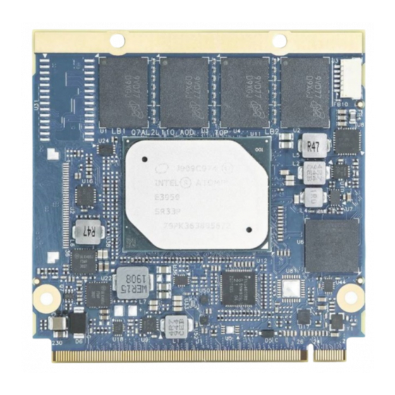
Module Views19
-
-
-
9 / Power on
43 -
-
Setup Menus45