beautypg.com
Manuals
Brands
S&T Manuals
Switch
Kontron RES2404-PTP-PoE
S&T Kontron RES2404-PTP-PoE Manuals
Manuals and User Guides for S&T Kontron RES2404-PTP-PoE. We have
1
S&T Kontron RES2404-PTP-PoE manual available for free PDF download: User Manual
S&T Kontron RES2404-PTP-PoE User Manual (35 pages)
Brand:
S&T
| Category:
Switch
| Size: 2.32 MB
Table of Contents
Table of Contents
9
1/ Introduction
11
Table 1: Product Variants
11
RES2404-PTP-Poe Operational View
12
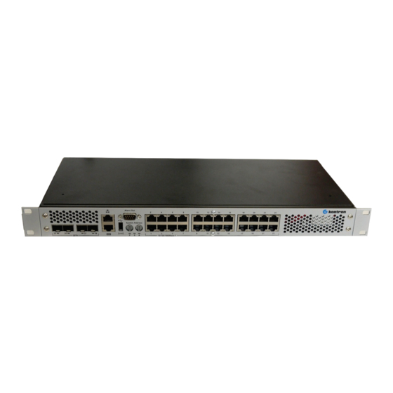
Figure 1: RES2404-PTP-Poe Operational Front View
12
Figure 2: RES2404-PTP-Poe Operational Back View
12
Figure 3: RES2404-PTP-Poe Inside View
12
Hardware Components
13
Software Components
13
Table 2: Software Specification
13
Technical Data
15
Table 3: Technical Data
15
Table 4: Environmental Conditions
16
2/ Getting Started with RES2404-PTP-Poe
17
Receipt of the Equipment
17
Checking the Packages
17
Unpacking
17
External Connectors
18
Ethernet Connectors (I/O Area)
18
Table 5: Pin Assignment Connector
18
Table 6: Signal Description
18
Figure 4: Ethernet Connector, Status Leds See Table 11: Status Leds
18
Small Form-Factor Pluggable (SFP+) Connector for 10Gbe
19
Table 7: SFP+ Connector
19
Figure 5: Small Form-Factor Pluggable (SFP+) Standard Connector for Gbe/10Gbe
19
Ethernet Port Mapping
20
Table 8: Ethernet Port Mapping
20
Dual RJ45 Connector
21
Table 9: Management-Port
21
Table 10: RS232
21
Figure 6: Dual RJ45 Connector (Red Circle)
21
3/ Device Management
22
Power and Status Leds
22
Table 11: Status Leds
22
Figure 7: Status Leds on RES2404-PTP-Poe (Red Circle)
22
Link Activity Poe Speed Leds for Gbe Ports
23
Power over Ethernet (Poe) Distribution
23
Table 12: Leds Link, Activity and Poe
23
Figure 8: Gbe-Ports with Leds
23
Figure 9: 10Gbe-Ports with Leds
23
Programming the Carrier ID (CID) with DIP Switches
24
Table 13: DIP Switch 1
24
Table 14: DIP Switch 2
24
Figure 10: Rotary DIP Switches
24
Restart by Pressing Reset Button
25
Table 15: POST Routines after Reset
25
Figure 11: Reset Button (in the Red Circle)
25
Alarm out
26
Table 16: Alarm out Connector
26
Figure 12: Alarm out Connector (in the Red Circle)
26
4/ Installation
27
Safety Requirements
27
Cooling
27
Mounting Variants
28
Precision Time Protocol (PTP)
28
Figure 13: Mounting Variants
28
Switch Configuration Access
29
Serial Port Access
29
Out-Of-Band Access Via Network
29
Figure 14: Admin Interfaces: Serial Service Port (Lower) and Ethernet Service Port (Upper)
29
In-Band Access Via Network
30
Firmware Administration
31
Firmware Description
31
Failsave Update
31
Update Procedure
31
Related Products
S&T Kontron KSwitch R3 UMP Series
S&T Kontron KSwitch D2
S&T kontron KSwitch D3
S&T kontron KSwitch D2 UG
S&T kontron KSwitch D1 UGP
S&T kontron KSwitch D3 UM
S&T kontron KSwitch D1 UGPD
S&T kontron KSwitch D4 MF
S&T kontron KSwitch D3 UMP
S&T kontron COMe-cVR6
S&T Categories
Computer Hardware
Switch
Desktop
Motherboard
GPS
More S&T Manuals