beautypg.com
Manuals
Brands
S&T Manuals
Control Unit
Kontron SDML-WLU0 Series
S&T Kontron SDML-WLU0 Series Manuals
Manuals and User Guides for S&T Kontron SDML-WLU0 Series. We have
1
S&T Kontron SDML-WLU0 Series manual available for free PDF download: User Manual
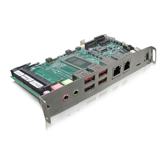
S&T Kontron SDML-WLU0 Series User Manual (85 pages)
Brand:
S&T
| Category:
Control Unit
| Size: 2.09 MB
Table of Contents
Symbols
6
For Your Safety
7
High Voltage Safety Instructions
7
Special Handling and Unpacking Instruction
7
Lithium Battery Precautions
8
General Instructions on Usage
8
Quality and Environmental Management
8
Disposal and Recycling
8
WEEE Compliance
8
Table of Contents
9
List of Tables
10
List of Figures
11
1 / Introduction
13
2 / Installation Procedures
14
Installing the Module
14
Display Safety Standards
15
Lithium Battery Replacement
15
3 / System Specifications
17
System Block Diagram
17
Figure 1: System Block Diagram SDML-WLU0 Series
17
Component Main Data
18
Table 1: Component Main Data
18
Environmental Conditions
19
Standards and Certifications
19
Table 2: Environmental Conditions
19
Table 3: Standards and Certifications
19
Processor Support
21
System Memory Support
21
Memory Operating Frequencies
21
Table 4: Processor Support
21
Table 5: Memory Operating Frequencies
21
On-Board Graphics Subsystem
22
Power Supply Voltage
22
Table 6: Display Maximum Resolution Support
22
Table 7: Supply Voltages
22
4 / Connector Locations
24
Top Side
24
Table 8: Jumper List
24
Table 9: Top Side Internal Connector Pin Assignment
24
Figure 2: Top Side
24
Table 10: M.2 Fixing Bolt List
25
Connector Panel Side
26
Table 11: Connector Panel Side Connector List
26
Table 12: Connector Panel Side Indicator List
26
Figure 3: Connector Panel Side
26
5 / Connector Definitions
27
6 / I/O-Area Connectors
28
Ethernet Connectors (CN10 & CN11)
28
Table 13: Pin Assignment Ethernet Connector CN10, CN11
28
Figure 4: Ethernet Connectors CN10, CN11
28
USB Connectors (I/O Area)
29
Table 14: Pin Assignment USB 3.1 / USB 3.0 / USB 2.0 Connectors CN12 - Top & Bottom, CN13 - Top & Bottom
29
Figure 5: USB 3.1 Connectors CN12 - Top & Bottom, CN13 - Top & Bottom
29
Figure 6: USB 2.0 High Speed Cable
29
Figure 7: USB 3.1 / USB 3.0 High Speed Cable
30
Micro SD Card Holder (CN14)
31
Table 15: Pin Assignment CN14
31
Figure 8: Micro SD Card Holder CN14
31
Optical S/PDIF Audio Port (CN15)
32
Table 16: Pin Assignment CN15
32
Figure 9: Optical S/PDIF Audio Port CN15
32
Audio Jack Line-Out Connector (CN16)
33
Table 17: Pin Assignment CN16
33
Figure 10: Audio Jack Line-Out Connector CN16
33
Audio Jack MIC-In Connector (CN17)
34
Table 18: Pin Assignment CN17
34
Figure 11: Audio Jack MIC-In Connector CN17
34
Power LED (LED1 Green)
35
Storage LED (LED1 Red)
35
7 / Internal Connectors
36
SDM Goldfinger (GF1)
36
Table 19: Pin Assignment GF1
36
Figure 12: SDM Goldfinger GF1
36
RTC Power Input Wafer (CN18)
38
Table 20: Pin Assignment CN18
38
Figure 13: RTC Power Input Wafer CN18
38
Fan Wafer (CN1)
39
Table 21: Pin Assignment CN1
39
Figure 14: Fan Wafer CN1
39
USB Connectors (Internal) (CN8)
40
Table 22: Pin Assignment CN8
40
Figure 15: USB 2.0 Port 8, 9 Pin Header CN8
40
P80 Header LPC (CN3)
41
Table 23: Pin Assignment CN3
41
Figure 16: P80 Header LPC CN3
41
SPI 10-Pin Header (CN4)
42
Table 24: Pin Assignment CN4
42
Figure 17: SPI 10-Pin Header CN4
42
Key B 2242 / 3042 / 2280 Slot (M2B1)
43
Table 25: Pin Assignment M2B1
43
Figure 18: M.2 Key B 2242 / 2042 / 2280 Slot M2B1
43
Key E 2230 / 3030 Slot (M2E1)
46
Table 26: Pin Assignment M2E1
46
Figure 19: M.2 Key E 2230 / 3030 Slot M2E1
46
Key M 2242 / 2280 Slot (M2M1)
49
Table 27: Pin Assignment M2M1
49
Figure 20: M.2 Key M 2242 / 2280 Slot M2M1
49
Table 28: Supplied Fixing Bolt Extensions and Fastening Screws
51
Figure 21: Location of M.2 Slots and Fixing Bolts
51
Table 29: Installation Configuration of M.2 Key B & M.2 Key E Modules
52
Table 30: Installation Configuration of M.2 Key M Modules
52
Micro SIM Card Holder for M.2 Key B (CN2)
53
Table 31: Pin Assignment CN2
53
Figure 22: Micro SIM Card Holder CN2
53
Key B / M.2 Key E Activity Indicator Header (CN9 & CN5)
54
Table 32: Pin Assignment CN9
54
Table 33: Pin Assignment CN5
54
Figure 23: M.2 Key B Activity Indicator Header CN9
54
Figure 24: M.2 Key E Activity Indicator Header CN5
54
Switches and Jumpers
55
MFG Mode Selection (JP1)
55
Table 34: Pin Assignment JP1
55
Figure 25: Jumper Connector
55
Figure 26: MFG Mode Selection JP1
55
USB Power Selection (JP3)
56
Key B Lane 0 Selection (JP4)
56
Table 35: Pin Assignment JP3
56
Table 36: Pin Assignment JP4
56
Figure 27: USB Power Selection JP3
56
Figure 28: M.2 Key B Lane 0 Selection JP4
56
Flash Descriptor Security Override Selection (JP5)
57
AT / ATX Power Mode Selection (JP6)
57
Table 37: Pin Assignment JP5
57
Table 38: Pin Assignment JP6
57
Figure 29: Flash Descriptor Security Override Selection JP5
57
Figure 30: at / ATX Power Mode Selection JP6
57
Clear CMOS Selection (JP7)
58
Table 39: Pin Assignment JP7
58
Figure 31: Clear CMOS Selection JP7
58
8 / Bios
59
Starting the Uefi BIOS
59
Table 40: Hotkeys Table
59
Starting the Uefi BIOS
60
Main Setup Menu
60
Table 41: Main Setup Menu Sub-Screens and Functions
60
Figure 32: BIOS Main Menu Screen System Data and Time
61
Figure 33: BIOS Main Menu - Main
62
Advanced Setup Menu
64
Figure 34: BIOS Advanced Menu
65
Figure 35: BIOS Advanced Menu - Display Configuration
66
Figure 36: BIOS Advanced Menu - CPU Chipset Configuration
67
Figure 37: BIOS Advanced Menu - Nvme Configuration
68
Figure 38: BIOS Advanced Menu - SATA Configuration
69
Figure 39: BIOS Advanced Menu - USB Configuration
70
Figure 40: BIOS Advanced Menu - Trusted Computing
71
Figure 41: BIOS Advanced Menu - H/W Monitor
72
Figure 42: BIOS Advanced Menu - H/W Monitor - Smart FAN Configuration
72
Figure 43: BIOS Advanced Menu - Network Stack
74
Power Setup Menu
75
Figure 44: BIOS Power Setup Menu
75
Figure 45: BIOS Power Setup Menu - Watchdog Timer Configuration
76
Boot Setup Menu
77
Figure 46: BIOS Boot Setup Menu
77
Security Setup Menu
78
Figure 47: BIOS Security Setup Menu
78
Figure 48: BIOS Security Setup Menu - - Secure Boot
79
Figure 49: BIOS Security Setup Menu - - Secure Boot - - Key Management
80
Save & Exit Setup Menu
83
Figure 50: BIOS Save & Exit Setup Menu
83
Appendix A: List of Acronyms
84
Table 42: List of Acronyms
84
About Kontron
85
Related Products
S&T kontron QSEVEN-Q7AL 2 Series
S&T Kontron SBOX-7210
S&T Kontron SBOX-5002
S&T Kontron SBOX-5210
S&T Kontron Mini ITX Skylake S/C236
S&T kontron FlatView Series
S&T kontron FlatClient Series
S&T Kontron B Series
S&T Kontron KSwitch R3 UMP Series
S&T Kontron CP3005 Series
S&T Categories
Computer Hardware
Switch
Desktop
Motherboard
GPS
More S&T Manuals