S&T Kontron SMARC-sXEL Manuals
Manuals and User Guides for S&T Kontron SMARC-sXEL. We have 1 S&T Kontron SMARC-sXEL manual available for free PDF download: User Manual
S&T Kontron SMARC-sXEL User Manual (108 pages)
Brand: S&T
|
Category: Computer Hardware
|
Size: 2.89 MB
Table of Contents
-
Symbols6
-
-
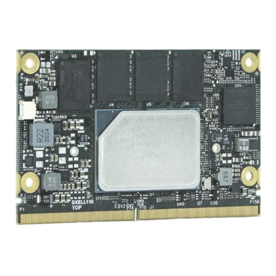
Heatspreader23
-
Compliance26
-
Mtbf27
-
-
-
-
Boot Select66
-
-
-
-
Setup Menus70
-
Chipset86
-
-
11 / Warranty
106