beautypg.com
Manuals
Brands
Schweitzer Engineering Laboratories Manuals
Power distribution unit
SEL-351A
Schweitzer Engineering Laboratories SEL-351A Manuals
Manuals and User Guides for Schweitzer Engineering Laboratories SEL-351A. We have
1
Schweitzer Engineering Laboratories SEL-351A manual available for free PDF download: Manual
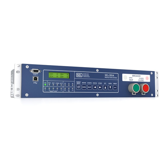
Schweitzer Engineering Laboratories SEL-351A Manual (666 pages)
Distribution Protection System
Brand:
Schweitzer Engineering Laboratories
| Category:
Power distribution unit
| Size: 6.42 MB
Table of Contents
Table of Contents
3
List of Tables
7
List of Figures
11
Preface
17
Section 1: Introduction and Specifications
17
Overview
17
SEL-351A Models
22
Table 1.1 SEL-351A Models
22
Table 1.2 SEL-351A-1 Models
22
Table 1.3 Major Differences-SEL-351, SEL-351A, and SEL-351A-1
23
Applications
26
Figure 1.1 SEL-351A Relays Applied Throughout the Power System
26
Hardware Connection Features
27
Figure 1.2 SEL-351A Inputs, Outputs, and Communications Ports
28
Communications Connections
29
Figure 1.3 SEL-351A Communications Connections Examples
29
Specifications
30
Section 2: Installation
35
Overview
35
Relay Mounting
36
Figure 2.1 SEL-351A Dimensions for Rack-Mount and Panel-Mount Models
37
Front-Panel and Rear-Panel Connection Diagrams
38
Figure 2.2 SEL-351A Rear-Panel Diagram-Conventional Terminal Blocks, Horizontal Example
39
Figure 2.3 SEL-351A Front-Panel Drawings (Rack Mount Relays)
40
Figure 2.4 SEL-351A Front-Panel Drawings (Panel-Mount Relays)
41
Figure 2.5 SEL-351A Front-Panel Drawing (Vertical Panel-Mount Relay, Model 0351A0X41) and Rear-Panel Drawing (Vertical Relay, Conventional Terminal Blocks, Model 0351A0041)
42
Figure 2.6 SEL-351A Rear-Panel Drawings-Connectorized Models 0351A0WH, 0351A0W3, or 0351A0W5 (Horizontal) and 0351A0W4 (Vertical)
43
Making Rear-Panel Connections
44
Figure 2.7 SEL-351A Plug-In Connector Coding (Top View; Model 0351A0W)
45
Figure 2.8 Broken-Delta Secondary Connection to Voltage Input VS, Wye-Connected Pts
50
Figure 2.10 Broken-Delta Secondary Connection to Voltage Input VS, Open-Delta Connected Pts
51
Figure 2.9 Resultant Voltage V S
52
Figure 2.11 Resultant Voltage
52
Table 2.1 Communications Cables to Connect the SEL-351A to Other Devices
53
SEL-351A AC/DC Connection Diagrams for Various Applications
54
Figure 2.12 SEL-351A Provides Overcurrent Protection and Reclosing for a Utility Distribution Feeder (Includes Fast Bus Trip Scheme) (Wye-Connected Pts)
54
Figure 2.13 SEL-351A Provides Overcurrent Protection for a Distribution Bus (Includes Fast Bus Trip Scheme) (Wye-Connected Pts)
55
Figure 2.14 SEL-351A Provides Directional Overcurrent Protection and Reclosing for a Transmission Line (Wye-Connected Pts)
56
Figure 2.16 SEL-351A Provides Overcurrent Protection for a Delta-Wye Transformer Bank (Wye-Connected Pts)
58
Figure 2.17 SEL-351A Provides Overcurrent Protection for a Transformer Bank with a Tertiary Winding (Wye-Connected Pts)
59
Figure 2.18 SEL-351A Provides Overcurrent Protection for an Industrial Distribution Feeder (Core-Balance Current Transformer Connected to Channel IN)
60
Figure 2.19 SEL-351A Provides Dedicated Breaker Failure Protection
61
Figure 2.20 SEL-351A Provides Overcurrent Protection for a High-Impedance or Low-Impedance Grounded System (Wye-Connected Pts)
62
Figure 2.21 SEL-351A Provides Overcurrent Protection for a Petersen Coil Grounded System (Wye-Connected Pts)
63
Figure 2.22 SEL-351A Provides Overcurrent Protection for an Ungrounded System (Wye-Connected Pts)
64
Figure 2.23 SEL-351A Provides Overcurrent Protection for an Ungrounded System (Open-Delta Connected Pts, Broken-Delta 3V0 Connection)
65
Figure 2.24 SEL-351A Provides Overcurrent Protection and Reclosing for a Utility Distribution Feeder (Open-Delta Connected Pts and Line-To-Ground Synchronism-Check Connection)
66
Figure 2.25 SEL-351A Provides Underfrequency Load Shedding, Overcurrent Protection, and Reclosing for a Utility Distribution Feeder (Single Voltage Connection)
67
Circuit Board Connections
68
Figure 2.26 Jumper, Connector, and Major Component Locations on the SEL-351A Main Board
69
Table 2.2 Output Contact Jumpers and Corresponding Output Contacts
70
Table 2.3 "Extra Alarm" Output Contacts and Corresponding Controlling Jumpers
70
Table 2.4 Required Position of Jumper JMP23 for Desired Output Contact OUT107 Operation
70
Table 2.5 Password and Breaker Jumper Positions for Standard Relay Shipments
71
Table 2.6 Password and Breaker Jumper Operation
71
Table 2.7 EIA-232 Serial Port Voltage Jumper Positions for Standard Relay Shipments
71
Figure 3.1 Levels 1 through 4 Phase Instantaneous Overcurrent Elements
74
Figure 3.2 Levels 5 through 6 Phase Instantaneous Overcurrent Elements
74
Figure 3.3 Levels 1 through 4 Phase Instantaneous/Definite-Time Overcurrent Elements (with Directional Control Option) (Not in SEL-351A-1)
76
Section 3: Overcurrent, Voltage, Synchronism Check, and Frequency Elements Instantaneous/Definite-Time Overcurrent Elements
78
Figure 3.4 Combined Single-Phase Instantaneous Overcurrent Elements
78
Figure 3.5 SEL-351A Nondirectional Instantaneous Overcurrent Element Pickup Time Curve
79
Figure 3.6 SEL-351A Nondirectional Instantaneous Overcurrent Element Reset Time Curve
79
Figure 3.7 Levels 1 through 4 Phase-To-Phase Instantaneous Overcurrent Elements
81
Figure 3.8 Levels 1 through 4 Neutral-Ground Instantaneous Overcurrent Elements (with Directional Control and Definite-Time Elements in SEL-351A)
82
Figure 3.9 Levels 5 through 6 Neutral-Ground Instantaneous Overcurrent Elements
82
Figure 3.10 Levels 1 through 4 Residual-Ground Instantaneous Overcurrent Elements (with Directional Control and Definite-Time Elements in SEL-351A)
84
Figure 3.11 Levels 5 through 6 Residual-Ground Instantaneous Overcurrent Elements
84
Figure 3.12 Levels 1 through 4 Negative-Sequence Instantaneous Overcurrent Elements (with Directional Control and Definite-Time Elements in SEL-351A)
87
Figure 3.13 Levels 5 through 6 Negative-Sequence Instantaneous Overcurrent Elements
87
Table 3.1 Available Phase Time-Overcurrent Elements
88
Table 3.2 Phase Time-Overcurrent Element (Maximum Phase) Settings
88
Time-Overcurrent Elements
88
Table 3.3 Phase Time-Overcurrent Element (Maximum Phase) Logic Outputs
89
Figure 3.15 A-Phase Time-Overcurrent Element 51AT (with Directional Control Option in SEL-351A)
93
Figure 3.16 B-Phase Time-Overcurrent Element 51BT (with Directional Control Option in SEL-351A)
93
Figure 3.17 C-Phase Time-Overcurrent Element 51CT (with Directional Control Option in SEL-351A)
94
Figure 3.18 Neutral-Ground Time-Overcurrent Element 51NT (with Directional Control Option in SEL-351A)
94
Table 3.4 Neutral-Ground Time-Overcurrent Element Settings
95
Figure 3.19 Residual-Ground Time-Overcurrent Element 51GT (with Directional Control Option in SEL-351A)
96
Table 3.5 Available Residual-Ground Time-Overcurrent Elements
96
Table 3.6 Residual-Ground Time-Overcurrent Element 51GT Settings
96
Figure 3.20 Residual-Ground Time-Overcurrent Element 51G2T (with Directional Control Option)
97
Table 3.7 Residual-Ground Time-Overcurrent Element 51G2T Settings
97
Figure 3.21 Negative-Sequence Time-Overcurrent Element 51QT (with Directional Control Option in SEL-351A)
98
Table 3.8 Negative-Sequence Time-Overcurrent Element Settings
99
Table 3.10 Voltage Elements Settings and Settings Ranges (Wye-Connected Pts)
100
Table 3.9 Voltage Values Used by Voltage Elements
100
Voltage Elements
100
Table 3.11 Voltage Elements Settings and Settings Ranges (VS Channel)
101
Table 3.12 Voltage Elements Settings and Settings Ranges (Delta-Connected Pts)
101
Figure 3.22 Single-Phase and Three-Phase Voltage Elements (Wye-Connected Pts)
103
Figure 3.23 Phase-To-Phase and Sequence Voltage Elements (Wye-Connected Pts)
104
Figure 3.24 Phase-To-Phase Voltage Elements (Delta-Connected Pts)
105
Figure 3.25 Sequence Voltage Elements (Delta-Connected Pts)
105
Figure 3.26 Channel VS Voltage Elements (Wye- or Delta-Connected Pts)
106
Synchronism Check Elements (Not in SEL-351A-1)
108
Table 3.13 Synchronism Check Elements Settings and Settings Ranges
108
Figure 3.27 Synchronism Check Voltage Window and Slip Frequency Elements
110
Figure 3.28 Synchronism Check Elements
111
Figure 3.29 Angle Difference between V
117
Figure 3.30 Undervoltage Block for Frequency Elements (Group Setting VNOM ≠ OFF)
121
Frequency Elements
121
Figure 3.32 Levels 1 through 6 Frequency Elements
122
Table 3.14 Frequency Elements Settings and Settings Ranges
123
Figure 4.1 Loss-Of-Potential Logic
127
Section 4: Loss-Of-Potential, Load Encroachment, and Directional Element Logic Loss-Of-Potential Logic (Not in the SEL-351A-1)
128
Load-Encroachment Logic (Not in SEL-351A-1)
130
Figure 4.2 Load-Encroachment Logic
130
Figure 4.3 Migration of Apparent Positive-Sequence Impedance for a Fault Condition
133
Directional Control for Neutral-Ground and Residual-Ground Overcurrent Elements (Not in SEL-351A-1)
135
Figure 4.4 General Logic Flow of Directional Control for Neutral-Ground and Residual-Ground Overcurrent Elements (Excluding Ungrounded/High-Impedance Grounded Systems)
136
Table 4.1 Available Ground Directional Elements
137
Figure 4.5 General Logic Flow of Directional Control for Neutral-Ground and Residual-Ground Overcurrent Elements (Ungrounded/High-Impedance Grounded Systems; ORDER
137
Table 4.2 Best Choice Ground Directional Element™ Logic
138
Table 4.3 Ground Directional Element Availability by Voltage Connection Settings
139
Figure 4.6 Internal Enables (32QE and 32QGE) Logic for Negative-Sequence Voltage-Polarized Directional Elements
144
Figure 4.7 Internal Enables (32VE and 32IE) Logic for Zero-Sequence Voltage-Polarized and Channel in Current-Polarized Directional Elements
145
Figure 4.8 Internal Enable (32NE) Logic for Zero-Sequence Voltage-Polarized Directional Elements (Low-Impedance Grounded, Petersen Coil Grounded, and Ungrounded/High-Impedance Grounded Systems)
146
Figure 4.9 Negative-Sequence Voltage-Polarized Directional Element for Neutral-Ground and Residual-Ground Overcurrent Elements
147
Figure 4.10 Zero-Sequence Voltage-Polarized Directional Element
148
Figure 4.11 Channel in Current-Polarized Directional Element
149
Figure 4.12 Zero-Sequence Voltage-Polarized Directional Element (Low-Impedance Grounded Systems)
150
Figure 4.13 Wattmetric and Incremental Conductance Directional Elements (Petersen Coil Grounded Systems)
151
Figure 4.14 Zero-Sequence Voltage-Polarized Directional Element (Ungrounded/High-Impedance Grounded Systems)
152
Figure 4.15 Routing of Directional Elements to Residual-Ground Overcurrent Elements
153
Figure 4.16 Routing of Direction Elements to Neutral-Ground Overcurrent Elements
153
Figure 4.17 Direction Forward/Reverse Logic for Residual-Ground Overcurrent Elements
154
Figure 4.18 Direction Forward/Reverse Logic for Neutral-Ground Overcurrent Elements
155
Directional Control for Negative-Sequence and Phase Overcurrent Elements (Not in SEL-351A-1)
156
Figure 4.19 General Logic Flow of Directional Control for Negative-Sequence and Phase Overcurrent Elements
156
Figure 4.20 Negative-Sequence Voltage-Polarized Directional Element for Negative-Sequence and Phase Overcurrent Elements
159
Figure 4.21 Positive-Sequence Voltage-Polarized Directional Element for Phase Overcurrent Elements
160
Figure 4.22 Routing of Directional Elements to Negative-Sequence and Phase Overcurrent Elements
161
Figure 4.23 Direction Forward/Reverse Logic for Negative-Sequence Overcurrent Elements
162
Figure 4.24 Direction Forward/Reverse Logic for Phase Overcurrent Elements
163
Directional Control Settings (Not in SEL-351A-1)
164
Table 4.4 Overcurrent Elements Controlled by Level Direction Settings DIR1-DIR4 (Corresponding Overcurrent Element Figure Numbers in Parentheses)
165
Figure 4.25 Zero-Sequence Impedance Network and Relay Polarity
173
Figure 4.26 Zero-Sequence Impedance Plot for Solidly-Grounded, Mostly Inductive System
173
Figure 4.27 Zero-Sequence Impedance Network for Ground Fault on Feeder
177
Figure 4.28 Wattmetric Element Operation for Ground Fault on Feeder
178
Table 4.5 Affect of Global Settings VSCONN and PTCONN on Petersen Coil Directional Elements
181
Directional Control Provided by Torque Control Settings (Not in SEL-351A-1)
183
Section 5: Trip and Target Logic Trip Logic
186
Figure 5.1 Trip Logic
186
Figure 5.2 Minimum Trip Duration Timer Operation (See Bottom of Figure 5.1)
187
Figure 5.3 Three-Pole Open Logic (Top) and Switch-Onto-Fault Logic (Bottom)
191
Switch-Onto-Fault (SOTF) Trip Logic
191
Front-Panel Target LEDS
194
Table 5.1 SEL-351A Front-Panel Target LED Definitions
194
Figure 5.4 Seal-In of Breaker Failure Occurrence for Message Display
197
Section 6: Close and Reclose Logic
199
Overview
199
Close Logic
200
Figure 6.1 Close Logic
200
Reclose Supervision Logic
203
Figure 6.2 Reclose Supervision Logic (Following Open Interval Time-Out)
203
Figure 6.3 Reclose Supervision Limit Timer Operation (Refer to Bottom of Figure 6.2)
204
Figure 6.4 SEL-351A Relays Installed at both Ends of a Transmission Line in a High-Speed Reclose Scheme
207
Reclosing Relay
210
Table 6.1 Relay Word Bit and Front-Panel Correspondence to Reclosing Relay States
211
Figure 6.5 Reclosing Relay States and General Operation
211
Table 6.2 Reclosing Relay Timer Settings and Setting Ranges
213
Figure 6.6 Reclosing Sequence from Reset to Lockout with Example Settings
214
Table 6.3 Shot Counter Correspondence to Relay Word Bits and Open Interval Times
216
Table 6.4 Reclosing Relay SEL OGIC Control Equation Settings
217
Table 6.5 Example Open Interval Time Settings
222
Figure 6.7 Reclose Blocking for Islanded Generator
222
Figure 6.8 Sequence Coordination between the SEL-351A and a Line Recloser
225
Figure 6.9 Operation of SEL-351A Shot Counter for Sequence Coordination
225
Section 7: Inputs, Outputs, Timers, and Othercontrol Logic
229
Overview
229
Optoisolated Inputs
230
Figure 7.1 Example Operation of Optoisolated Inputs IN101-IN106
230
Figure 7.2 Circuit Breaker Auxiliary Contact and Reclose Enable Switch Connected to Optoisolated Inputs IN101 and IN102
231
Local Control Switches (Only on Models with LCD)
233
Table 7.1 Correspondence between Local Control Switch Positions and Label Settings
233
Figure 7.3 Local Control Switches Drive Local Bits LB1-LB16
233
Table 7.2 Correspondence between Local Control Switch Types and Required Label Settings
234
Figure 7.4 Local Control Switch Configured as an ON/OFF Switch
234
Figure 7.5 Local Control Switch Configured as an OFF/MOMENTARY Switch
234
Figure 7.6 Local Control Switch Configured as an ON/OFF/MOMENTARY Switch
234
Figure 7.7 Configured Manual Trip Switch Drives Local Bit LB3
235
Figure 7.8 Configured Manual Close Switch Drives Local Bit LB4
235
Remote Control Switches
237
Figure 7.9 Remote Control Switches Drive Remote Bits RB1-RB16
237
Latch Control Switches
239
Figure 7.10 Traditional Latching Relay
239
Figure 7.11 Latch Control Switches Drive Latch Bits LT1-LT16
239
Figure 7.12 SCADA Contact Pulses Input IN104 to Enable/Disable Reclosing Relay
240
Figure 7.13 Latch Control Switch Controlled by a Single Input to Enable/Disable Reclosing
240
Figure 7.14 Latch Control Switch Operation Time Line
242
Figure 7.15 Time Line for Reset of Latch Bit LT2 after Active Setting Group Change
243
Figure 7.16 Latch Control Switch (with Time Delay Feedback) Controlled by a Single Input to Enable/Disable Reclosing
244
Figure 7.17 Latch Control Switch (with Time Delay Feedback) Operation Time Line
245
Multiple Setting Groups
246
Table 7.3 Definitions for Active Setting Group Indication Relay Word Bits SG1 through SG6
246
Table 7.4 Definitions for Active Setting Group Switching
246
Table 7.5 SEL OGIC Control Equation Settings for Switching Active Setting Group between Setting Groups 1 and
248
Figure 7.18 SCADA Contact Pulses Input IN105 to Switch Active Setting Group between Setting Groups 1 and
248
Figure 7.19 SEL OGIC Control Equation Variable Timer SV8T Used in Setting Group Switching
248
Table 7.6 Active Setting Group Switching Input Logic
250
Figure 7.20 Active Setting Group Switching (with Single Input) Time Line
250
Figure 7.21 Rotating Selector Switch Connected to Inputs IN101, IN102, and IN103 for Active Setting Group Switching
251
Figure 7.22 Active Setting Group Switching (with Rotating Selector Switch) Time Line
253
SEL OGIC Control Equation Variables/Timers
255
Figure 7.25 Dedicated Breaker Failure Scheme Created with SEL Control Equation Variables/Timers
257
Output Contacts
259
Figure 7.26 Logic Flow for Example Output Contact Operation
261
Rotating Default Display (Only on Models with LCD)
262
Figure 7.27 Traditional Panel Light Installations
262
Figure 7.28 Rotating Default Display Replaces Traditional Panel Light Installations
263
Table 7.8 Mnemonic Settings for Metering on the Rotating Default Display
269
Section 8: Breaker Monitor and Metering
272
Table 7.9 Mnemonic Settings for Breaker Wear Monitor Values on the Rotating Default Display
273
Table 7.10 Mnemonic Settings for Time-Overcurrent (TOC) Element Pickups on the Rotating Default Display
275
Table 7.11 Mnemonic Settings for Time-Overcurrent (TOC) Element Pickups Using the Same-Line-Label Format on the Rotating Default Display
275
Overview
279
Breaker Monitor
280
Table 8.1 Breaker Maintenance Information for a 25 Kv Circuit Breaker
280
Figure 8.1 Plotted Breaker Maintenance Points for a 25 Kv Circuit Breaker
281
Table 8.2 Breaker Monitor Settings and Settings Ranges
282
Figure 8.2 SEL-351A Breaker Maintenance Curve for a 25 Kv Circuit Breaker
283
Figure 8.3 Operation of SEL OGIC Control Equation Breaker Monitor Initiation Setting
284
Figure 8.4 Breaker Monitor Accumulates 10 Percent Wear
286
Figure 8.5 Breaker Monitor Accumulates 25 Percent Wear
287
Figure 8.6 Breaker Monitor Accumulates 50 Percent Wear
288
Figure 8.7 Breaker Monitor Accumulates 100 Percent Wear
289
Figure 8.8 Input IN106 Connected to Trip Bus for Breaker Monitor Initiation
292
Figure 8.9 DC Under- and Overvoltage Elements
293
Station DC Battery Monitor (Not in SEL-351A-1)
293
Demand Metering
298
Figure 8.11 Response of Thermal and Rolling Demand Meters to a Step Input (Setting DMTC = 15 Minutes)
299
Figure 8.12 Voltage V S Applied to Series RC Circuit
300
Table 8.3 Demand Meter Settings and Settings Range
302
Figure 8.13 Demand Current Logic Outputs
303
Figure 8.14 Raise Pickup of Residual-Ground Time-Overcurrent Element for Unbalance Current
303
Energy Metering
306
Maximum/Minimum Metering
307
Table 8.4 Operation of Maximum/Minimum Metering with Directional Power Quantities
307
Small Signal Cutoff for Metering
309
Synchrophasor Metering
310
Section 9: Setting the Relay
311
Overview
311
Table 9.1 Serial Port SET Commands
311
Settings Changes Via the Front Panel (Only on Models with LCD)
312
Settings Changes Via the Serial Port
312
Table 9.2 Set Command Editing Keystrokes
312
Time-Overcurrent Curves
314
Table 9.3 Equations Associated with U.S. Curves
314
Table 9.4 Equations Associated with IEC Curves
314
Figure 9.1 U.S. Moderately Inverse Curve: U1
316
Figure 9.2 U.S. Inverse Curve: U2
317
Figure 9.3 U.S. very Inverse Curve: U3
318
Figure 9.4 U.S. Extremely Inverse Curve: U4
319
Figure 9.5 U.S. Short-Time Inverse Curve: U5
320
Figure 9.6 I.E.C. Class a Curve (Standard Inverse): C1
321
Figure 9.7 I.E.C. Class B Curve (very Inverse): C2
322
Figure 9.8 I.E.C. Class C Curve (Extremely Inverse): C3
323
Figure 9.9 I.E.C. Long-Time Inverse Curve: C4
324
Figure 9.10 I.E.C. Short-Time Inverse Curve: C5
325
Relay Word Bits (Used in SEL OGIC Control Equations)
326
Table 9.5 SEL-351A Relay Word Bits
326
Table 9.6 Relay Word Bit Definitions for SEL-351A
328
Settings Explanations
344
Table 9.7 Main Relay Functions that Change with VSCONN, When PTCONN = WYE
347
Table 9.8 Main Relay Functions that Change with VSCONN, When PTCONN = DELTA
348
Table 9.9 Main Relay Functions that Change with VNOM = off
348
Figure 9.11 Operation of DELTA and 3V0 Relay Word Bits
348
Figure 9.12 Hybrid Power System with Neutral-Ground Resistor
350
Settings Sheets
352
SEL-351A Settings Sheets
353
SEL-351A-1 Settings Sheets
385
Section 10: Serial Port Communications and Commands
411
Overview
411
Table 10.1 SEL-351A Available Serial Ports
411
Port Connector and Communications Cables
412
Table 10.2 Pinout Functions for EIA-232 Serial Ports 2, 3, and
412
Table 10.3 Terminal Functions for EIA-485 Serial Port 1
412
Figure 10.1 DB-9 Connector Pinout for EIA-232 Serial Ports
412
Table 10.4 Serial Communications Port Pin/Terminal Function Definitions
414
Communications Protocol
416
Serial Port Automatic Messages
419
Table 10.5 Serial Port Automatic Messages
419
Serial Port Access Levels
420
Command Summary
422
Table 10.6 Serial Port Command Summary
422
Command Explanations
424
Table 10.7 SEL-351A Word and Its Correspondence to TAR Command
441
Table 10.8 SEL-351A Control Subcommands
447
Table 10.9 Valid Password Characters
448
SEL-351A Command Summary
451
Section 11: Front-Panel Interface (Only on Models with LCD)
455
Overview
455
Front-Panel Pushbutton Operation
456
Figure 11.1 Front-Panel Pushbuttons-Overview
456
Figure 11.2 Front-Panel Pushbuttons-Primary Functions
457
Figure 11.3 Front-Panel Pushbuttons-Primary Functions (Continued)
458
Figure 11.4 Front-Panel Pushbuttons-Secondary Functions
459
Functions Unique to the Front-Panel Interface
460
Figure 11.5 Local Control Switch Configured as an ON/OFF Switch
462
Figure 11.6 Local Control Switch Configured as an OFF/MOMENTARY Switch
462
Figure 11.7 Local Control Switch Configured as an ON/OFF/MOMENTARY Switch
462
Rotating Default Display
466
Section 12: Standard Event Reports and SER
473
Overview
473
Standard 15/30-Cycle Event Reports
474
Figure 12.1 Example Event Summary
476
Table 12.1 Event Types
477
Figure 12.2 Example Synchrophasor-Level Precise Event Report 1/16-Cycle Resolution
480
Table 12.2 Standard Event Report Current, Voltage, and Frequency Columns
481
Table 12.3 Output, Input, and Protection, and Control Element Event Report Columns
484
Sequential Events Recorder (SER) Report
493
Example Standard 15-Cycle Event Report
496
Figure 12.4 Example Partial Event Report with Delta-Connected Pts
499
Figure 12.5 Derivation of Event Report Current Values and RMS Current Values from Sampled Current Waveform
500
Figure 12.6 Derivation of Phasor RMS Current Values from Event Report Current Values
501
Example Sequential Events Recorder (SER) Report
502
Figure 12.7 Example Sequential Events Recorder (SER) Event Report
502
Section 13: Testing and Troubleshooting
505
Overview
505
Testing Philosophy
506
Testing Methods and Tools
509
Table 13.1 Test Features Provided by the Relay
509
Table 13.2 Resultant Scale Factors for Input Module
510
Figure 13.1 Low-Level Test Interface (J1 or J10) Connector
510
Relay Self-Tests
513
Table 13.3 Relay Self-Tests
513
Relay Troubleshooting
515
Relay Calibration
517
Factory Assistance
518
Table A.1 SEL-351A Firmware Revision History
519
Appendix A: Firmware and Manual Versions Firmware
520
Table A.2 SEL-351A-1 Firmware Revision History
523
Table A.3 Instruction Manual Revision History
525
Appendix B: Firmware Upgrade Instructions
535
Overview
535
Relay Firmware Upgrade Instructions
536
Figure B.1 Establishing a Connection
538
Figure B.2 Determining the Computer Serial Port
538
Figure B.3 Determining Communications Parameters for the Computer
539
Figure B.4 Setting Terminal Emulation
539
Figure B.5 Terminal Emulation Startup Prompt
540
Figure B.6 Correcting the Port Setting
540
Figure B.7 Correcting the Communications Parameters
541
Figure B.8 Preparing Hyperterminal for ID Command Display
542
Figure B.9 List of Commands Available in SEL
543
Figure B.10 Matching Computer to Relay Parameters
544
Figure B.11 Example Receive File Dialog Box
545
Figure B.12 Example Filename Identifying Old Firmware Version
545
Figure B.13 Downloading Old Firmware
545
Figure B.14 Selecting New Firmware to Send to the Relay
547
Figure B.15 Transferring New Firmware to the Relay
547
Table B.1 Troubleshooting New Firmware Upload
548
Figure B.16 Preparing Hyperterminal for ID Command Display
551
Ethernet Port Firmware Upgrade Instructions
553
Figure B.17 Establishing an FTP Connection
554
Figure B.18 Alternate Method of Establishing an FTP Connection
555
Figure B.19 Read (Open) File
555
Figure B.20 Page Cannot be Displayed Window
556
Appendix C: SEL Distributed Port Switch Protocol
559
Overview
559
Settings
560
Operation
561
Appendix D: Configuration, Fast Meter, and Fast Operate Commands
563
Overview
563
Message Lists
564
Table D.1 Binary Message List
564
Table D.2 ASCII Configuration Message List
564
Message Definitions
565
Table D.3 A5C0 Relay Definition Block
565
Table D.4 A5C1 Fast Meter Configuration Block
565
Table D.5 A5D1 Fast Meter Data Block
567
Table D.6 A5C2/A5C3 Demand/Peak Demand Fast Meter Configuration Messages
567
Table D.7 A5D2/A5D3 Demand/Peak Demand Fast Meter Message
570
Table D.8 A5CE Fast Operate Configuration Block
571
Table D.9 A5E0 Fast Operate Remote Bit Control
572
Table D.10 A5E3 Fast Operate Breaker Control
573
Table D.11 A5CD Fast Operate Reset Definition Block
573
Table D.12 A5ED Fast Operate Reset Command
574
Appendix E: Compressed ASCII Commands
577
Overview
577
CASCII Command-General Format
578
CASCII Command-SEL-351A
580
CSTATUS Command-SEL-351A
581
CHISTORY Command-SEL-351A
582
CEVENT Command-SEL-351A
583
Table E.1 Mapping Labels to Bits
585
Appendix F: Setting Negative-Sequence Overcurrent Elements
587
Setting Negative-Sequence Definite-Time Overcurrent Elements
587
Setting Negative-Sequence Time-Overcurrent Elements
588
Figure F.1 Minimum Response Time Added to a Negative-Sequence Time-Overcurrent Element 51QT
588
Coordinating Negative-Sequence Overcurrent Elements
589
Figure F.2 Distribution Feeder Protective Devices
590
Figure F.3 Traditional Phase Coordination
590
Figure F.4 Phase-To-Phase Fault Coordination
591
Figure F.5 Negative-Sequence Overcurrent Element Derived from "Equivalent" Phase Overcurrent Element, 51EP
592
Other Negative-Sequence Overcurrent Element References
594
Appendix G: Setting SEL OGIC Control Equations
595
Overview
595
Relay Word Bits
596
SEL OGIC Control Equations
598
Figure G.1 Result of Rising-Edge Operators on Individual Elements in Setting er
601
Figure G.2 Result of Falling-Edge Operator on a Deasserting Underfrequency Element
602
Table G.2 SEL OGIC Control Equation Settings Limitations
604
Processing Order and Processing Interval
606
Table G.3 Processing Order of Relay Elements and Logic (Top to Bottom)
606
Appendix H: Distributed Network Protocol
609
Overview
609
Configuration
610
Table H.1 Settings to Configure a Port for DNP
610
Table H.2 Settings to Configure a Port for Extended Mode DNP
610
EIA-232 Physical Layer Operation
612
Data-Link Operation
613
Data Access Method
614
Table H.3 Data Access Methods
614
Device Profile
615
Table H.4 SEL-351A DNP3 Device Profile
615
Object Table
617
Table H.5 SEL-351A DNP Object Table
617
Data Map
622
Table H.6 SEL-351A DNP Data Map
622
Table H.7 Analog 105 Upper-Byte Definitions
625
Table H.8 Analog 105 Lower-Byte Definitions
625
Table H.9 Control Field
625
Point Remapping
628
DNP Settings Sheets
629
SET: Appendix I: Using the SEL-251 and SEL-267 Relay Settings in the SEL-351A Relay
631
Appendix Jsel-351A Fast SER Protocol
637
Overview
637
Make Sequential Events Recorder (SER) Settings with Care
638
Recommended Message Usage
639
Functions and Function Codes
640
Table J.3 Message Format for Function Code 18
641
Table J.4 Message if SER Records Are Lost
642
Table J.5 Acknowledge Message Format
643
AC SEL ERATOR Quickset SEL-5030 Software
646
Appendix K: ACSELERATOR Quickset SEL-5030 Software
646
AC SEL ERATOR Quickset System Requirements
646
Installation
647
Starting AC SEL ERATOR Quickset
648
Appendix Lsel Synchrophasors
649
Overview
649
Introduction
650
Synchrophasor Measurement
651
Figure L.1 Phase Reference
651
External Equipment Compensation
652
Figure L.2 Waveform at Relay Terminals May Have Phase Shift
652
Figure L.3 Correction of Measured Phase Angle
652
Protocol Operation
653
Table L.1 SEL Fast Message Protocol Format
653
Table L.2 Unsolicited Fast Message Enable Packet
654
Table L.3 Unsolicited Fast Message Disable Packet
654
Table L.4 Permissible Message Periods Requested by Enable Message
655
Settings
656
Table L.5 SEL-351A Global Settings for Synchrophasors
656
Table L.6 SEL-351A Serial Port Settings for Synchrophasors
656
Synchrophasor Relay Word Bits
659
Table L.7 Time Synchronization Relay Word Bits
659
View Synchrophasors by Using the MET PM Command
660
Figure L.4 Sample MET PM Command Response
661
Communications Bandwidth
662
Table L.8 SEL Fast Message Voltage and Current Selections Based on PHDATAV and PHDATAI
662
Related Products
Schweitzer Engineering Laboratories SEL-351S
Schweitzer Engineering Laboratories SEL-351-1
Schweitzer Engineering Laboratories SEL-351-0
Schweitzer Engineering Laboratories SEL-351-3
Schweitzer Engineering Laboratories SEL-351-2
Schweitzer Engineering Laboratories SEL-351-4
Schweitzer Engineering Laboratories SEL-351-5
Schweitzer Engineering Laboratories SEL-351-6
Schweitzer Engineering Laboratories SEL-351-7
Schweitzer Engineering Laboratories SEL-351R
Schweitzer Engineering Laboratories Categories
Relays
Computer Hardware
Transceiver
Protection Device
Measuring Instruments
More Schweitzer Engineering Laboratories Manuals