beautypg.com
Manuals
Brands
Schweitzer Engineering Laboratories Manuals
Relays
SEL-787
Schweitzer Engineering Laboratories SEL-787 Manuals
Manuals and User Guides for Schweitzer Engineering Laboratories SEL-787. We have
1
Schweitzer Engineering Laboratories SEL-787 manual available for free PDF download: Instruction Manual
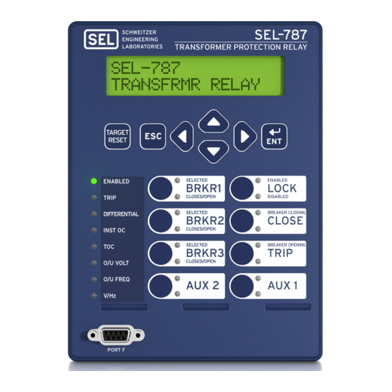
Schweitzer Engineering Laboratories SEL-787 Instruction Manual (564 pages)
Transformer Protection Relay
Brand:
Schweitzer Engineering Laboratories
| Category:
Relays
| Size: 5.31 MB
Table of Contents
Table of Contents
3
Appendix A: Firmware and Manual Versions
9
Firmware
9
Overview
13
Settings
14
Overview
17
Overview
19
Models, Options, and Accessories
26
Applications
28
Table 1.1 SEL-787 Serial Port Settings
29
Figure 1.1 Response Header
29
Figure 1.2 STA Command Response-No Devicenet Communications Card or with EIA-232/EIA-485 Communications Card
30
Figure 1.3 STA Command Response-With Devicenet Communications Card
30
Definitions
30
Appendix D: DNP3 Communications
37
Overview
37
I/O Configuration
38
Figure 2.1 Relay Panel-Mount Dimensions
38
Figure 2.2 Slot Allocations for Different Cards
39
Table 2.1 Communication Ports
40
Table 2.2 Communication Card Interfaces and Connectors
41
Table 2.3 Current Card Terminal Allocation
41
Table 2.4 Current/Voltage Card Terminal Allocation
42
Table 2.5 Four Analog Input/Four Analog Output (4 AI/4 AO) Card Terminal Allocation
42
Table 2.6 I/O (3 DI/4 DO/1 AO) Card Terminal Allocation
42
Table 2.7 RTD (10 RTD) Card Terminal Allocation
43
Table 2.8 Four Digital Input/Four Digital Output (4 DI/4 DO) Card Terminal Allocation
43
Table 2.9 Eight Digital Input (8 DI) Card Terminal Allocation
44
Figure 2.3 Circuit Board of Analog I/O Board, Showing Jumper Selection
45
Figure 2.4 JMP1 through JMP4 Locations on 4 AI/4 AO Board
46
Figure 2.5 Current Output Jumpers
46
Figure 2.6 Voltage Output Jumpers
46
Table 2.10 Jumper Functions and Default Positions
47
Figure 2.8 Rear-Panel Connections of Selected Cards
48
Rear-Panel Connections
49
Figure 2.9 Dual-Fiber, Ethernet, EIA-232 Communication, 3 DI/4 DO/1 AO, and Current/Voltage (1 ACI/3 AVI) Option
49
Figure 2.10 Single Copper Ethernet, 8 DI, RTD, and 4 AI/4 AO Option
50
Figure 2.11 Devicenet, Fast Hybrid 4 DI/4 DO, and Current/Voltage Option
50
Figure 2.12 Control I/O Connections-4 AI/4 AO Option in Slot D and Fiber-Optic Port in Slot B
52
Figure 2.13 Control I/O Connections-Internal RTD Option
52
AC/DC Control Connection Diagrams
53
Figure 2.14 Output OUT103 Relay Output Contact Configuration
53
Figure 2.15 OUT103 Contact Fail-Safe and Nonfail-Safe Options
53
Figure 2.16 Single-Phase Voltage Connections
54
Figure 2.17 Voltage Connections
55
Figure 2.18 Typical Current Connections
56
Figure 2.19 SEL-787 Provides Basic Two-Winding Transformer Differential Protection
57
Figure 2.20 SEL-787 Provides Two-Winding Transformer Differential Protection with REF (Restricted Earth Fault) Protection
58
Figure 2.21 SEL-787 Provides Two-Winding Transformer Differential Protection with REF and Voltage-Based Protection
59
Figure 2.22 SEL-787 Provides Autotransformer Differential Protection, Including REF Protection
60
Figure 2.23 Example DC Connections
61
Upgrade Instructions
62
Overview
63
Table 3.1 SEL Software Solutions
63
Setup
64
Figure 3.1 Serial Port Communication Dialog Box
64
Figure 3.2 Serial Port Communication Parameters Dialog Box
64
Terminal
65
Figure 3.3 Network Communication Parameters Dialog Box
65
Figure 3.4 Tools Menu
65
Settings Database Management and Drivers
66
Figure 3.5 Device Response to the ID Command
66
Settings
68
Table 3.3 File/Tools Menus
68
Figure 3.6 Selection of Drivers
69
Figure 3.7 Update Part Number
69
Figure 3.8 New Setting Screen
70
Figure 3.9 Expressions Created with Expression Builder
71
Event Analysis
73
Figure 3.10 Composite Screens for Retrieving Events
73
Meter and Control
74
Figure 3.11 Saving the Retrieved Event
74
Figure 3.12 Device Overview Screen
75
Figure 3.13 Control Screen
76
Figure 3.14 Remote Operation Selection
76
Table 3.4 Help
77
Overview
79
Application Data
80
Table 4.1 Identifier Settings
80
Table 4.2 Configurations and Ratings (Phase Cts, Power Transformer)
81
Table 4.3 Configurations and Ratings (Optional Neutral CT, Phase PT)
82
Basic Protection
83
Figure 4.1 Percentage Restraint Differential Characteristic
84
Figure 4.2 Winding 1 Compensated Currents
85
Figure 4.3 Differential Element (87-1) Quantities
85
Figure 4.4 Differential Element Decision Logic
87
Table 4.4 Differential Element Settings
88
Figure 4.5 Differential Element Harmonic Blocking Logic
88
Figure 4.6 Differential Current Alarm Logic Diagram
89
Figure 4.7 Winding Connections, Phase Shifts, and Compensation Direction
94
Figure 4.8 Example 1 for Wnctc Selection
96
Figure 4.10 REF Enable Logic
105
Figure 4.11 REF Directional Element
106
Figure 4.12 REF Protection Output (Extremely Inverse-Time O
107
Table 4.5 Restricted Earth Fault Settings
107
Figure 4.13 REF Function, REF1POL Setting Guide
108
Table 4.6 Winding N Maximum Phase Overcurrent Settings (N = 1 or 2)
109
Figure 4.14 Instantaneous Overcurrent Element Logic
110
Table 4.7 Winding N Residual Overcurrent Settings (N = 1, 2)
111
Table 4.8 Winding N Negative-Sequence Overcurrent Settings (N = 1 or 2)
111
Figure 4.15 Maximum Phase Time-Overcurrent Elements 51P1T and 51P2T
112
Table 4.9 Winding N Maximum Phase Time-Overcurrent (N = 1 or 2)
112
Table 4.10 Residual Time-Overcurrent Settings (N = 1 or 2)
112
Figure 4.16 Residual Time-Overcurrent Elements 51G1T and 51G2T
113
Table 4.11 Winding N Negative-Sequence Time-Overcurrent Settings (N = 1, 2)
113
Figure 4.17 Negative-Sequence Time-Overcurrent Element 51Q1T and 51Q2T
114
Table 4.12 Neutral Overcurrent Settings
114
Table 4.13 Neutral Time-Overcurrent Settings
114
Figure 4.18 Neutral Time-Overcurrent Elements 51N1T and 51N2T
115
Table 4.14 Equations Associated with U.S. Curves
116
Table 4.15 Equations Associated with IEC Curves
116
Figure 4.19 U.S. Moderately Inverse Curve: U1
117
Figure 4.20 U.S. Inverse Curve: U2
118
Figure 4.21 U.S. very Inverse Curve: U3
119
Figure 4.22 U.S. Extremely Inverse Curve: U4
120
Figure 4.23 U.S. Short-Time Inverse Curve: U5
121
Figure 4.24 I.E.C. Class a Curve (Standard Inverse): C1
122
Figure 4.25 I.E.C. Class B Curve (very Inverse): C2
123
Figure 4.26 I.E.C. Class C Curve (Extremely Inverse): C3
124
Figure 4.27 I.E.C. Long-Time Inverse Curve: C4
125
Figure 4.28 I.E.C. Short-Time Inverse Curve: C5
126
RTD-Based Protection
127
Table 4.16 RTD Settings
127
Table 4.17 RTD Resistance Versus Temperature
128
Voltage-Based Protection
129
Table 4.18 Undervoltage Settings
129
Table 4.19 Overvoltage Settings
129
Figure 4.30 Overvoltage Element Logic
130
Figure 4.31 Overvoltage Element Logic
131
Figure 4.32 Dual-Level Volts/Hertz Time-Delay Characteristic 24CCS
132
Figure 4.33 Composite Inverse/Definite-Time Overexcitation Characteristic, 24CCS
132
Table 4.20 Volts Per Hertz Settings
133
Figure 4.35 Volts/Hertz Inverse-Time Characteristic, 24IC
135
Figure 4.36 Volts/Hertz Inverse-Time Characteristic, 24IC
135
Figure 4.37 Three-Phase Power Elements Logic
137
Table 4.21 Power Element Settings
137
Figure 4.38 Power Elements Operation in the Real/Reactive Power Plane
138
Figure 4.39 Over- and Underfrequency Element Logic
139
Table 4.22 Frequency Settings
139
Demand Metering
141
Figure 4.40 Loss-Of-Potential (LOP) Logic
141
Figure 4.41 Demand Current Logic Outputs
142
Table 4.23 Demand Meter Settings
142
Figure 4.42 Response of Thermal and Rolling Demand Meters to a Step Input
143
Figure 4.43 Voltage V S Applied to Series RC Circuit
144
Table 4.24 Trip/Close Logic Settings
146
Figure 4.44 Trip Logic
147
Figure 4.45 Close Logic
149
Logic Settings (SET L Command)
150
Table 4.25 Enable Settings
150
Figure 4.47 Logic Diagram of a Latch Switch
151
Table 4.26 Latch Bits Equation Settings
151
Figure 4.49 Result of Falling-Edge Operator on a Deasserting Input
155
Table 4.30 Counter Input/Output Description
157
Figure 4.52 Example of the Effects of the Input Precedence
158
Table 4.31 Order of Precedence of the Control Inputs
158
Table 4.32 Control Output Equations and Contact Behavior Settings
159
Table 4.33 General Global Settings
160
Figure 4.53 Phase Rotation Setting
161
Table 4.34 Setting Group Selection
162
Table 4.35 Breaker Failure Setting
162
Figure 4.55 Analog Input Card Adaptive Name
163
Table 4.36 Summary of Steps
164
Figure 4.56 Settings to Configure Input 1 as a 4-20 Ma Transducer Measuring Temperatures
166
Table 4.37 Analog Input Card in Slot 3
166
Figure 4.57 Analog Output Number Allocation
167
Table 4.38 Output Setting for a Card in Slot 3
167
Figure 4.58 Analog Output Settings
168
Figure 4.59 DC Mode Processing
168
Figure 4.61 Timing Diagram for Debounce Timer Operation When Operating in AC Mode
169
Figure 4.60 AC Mode Processing
169
Table 4.39 Slot C Input Debounce Settings
169
Table 4.40 Data Reset Setting
170
Table 4.41 Setting Change Disable Setting
170
Port Settings (SET P Command)
170
Table 4.43 Ethernet Port Settings
171
Table 4.44 Fiber-Optic Serial Port Settings
172
Table 4.45 Rear-Panel Serial Port Settings
172
Table 4.46 Rear-Panel Serial Port (EIA-232/EIA-485) Settings
172
Table 4.47 Rear-Panel Devicenet Port Settings
173
Table 4.48 Display Point and Local Bit Default Settings
174
Table 4.49 Front-Panel General Settings
174
Front-Panel Settings (SET F Command)
174
Table 4.50 LCD Display Point Settings
175
Table 4.51 Settings that Always, Never, or Conditionally Hide a Display Point
176
Table 4.52 Entries for the Four Strings
176
Figure 4.62 Display Point Settings
177
Figure 4.63 Front-Panel Display-Both HV and LV Breakers Open
177
Figure 4.64 Front-Panel Display-HV Breaker Closed, LV Breaker Open
177
Figure 4.65 Front-Panel Display-Both HV and LV Breakers Closed
177
Figure 4.66 Front-Panel Display-HV Breaker Open, LV Breaker Closed
178
Figure 4.67 Front-Panel Display-HV Breaker Open, LV Breaker Closed
178
Figure 4.68 Front-Panel Display for a Binary Entry in the Name String Only
178
Table 4.53 Binary Entry in the Name String Only
178
Figure 4.69 Front-Panel Display for an Analog Entry in the Name String Only
179
Table 4.54 Analog Entry in the Name String Only
179
Table 4.55 Entry in the Name String and the Alias Strings
179
Figure 4.70 Front-Panel Display for an Entry in (A) Boolean Name and Alias Strings and (B) Analog Name and User Text and Formatting Strings
180
Figure 4.71 Front-Panel Display for an Entry in (A) Boolean Name and Alias Strings and (B) Analog Name, User Text and Formatting Strings, and Engineering Units
180
Table 4.56 Example Settings and Displays
180
Figure 4.72 Adding Temperature Measurement Display Points
181
Figure 4.74 Adding Two Local Bits
182
Table 4.57 Target LED Settings
183
Table 4.58 Pushbutton LED Settings
184
Table 4.59 Auto-Removal Settings
184
Report Settings (SET R Command)
184
Table 4.60 SER Trigger Settings
185
Table 4.61 Enable Alias Settings
185
Table 4.62 SET R SER Alias Settings
186
Table 4.63 Event Report Settings
186
Table 4.64 Load Profile Settings
186
Table 4.65 DNP Map Settings
187
Modbus Map Settings (SET M Command)
188
Table 4.66 User Map Register Settings
188
Overview
189
Figure 5.1 Complex Power Measurement Conventions
190
Metering
191
Table 5.1 Measured Fundamental Meter Values
191
Figure 5.2 METER Command Report with Voltage Option
192
Table 5.2 Measured Differential Meter Values
192
Figure 5.3 METER DIF (Differential) Command Report
193
Figure 5.4 METER T Command Report with Rtds
193
Table 5.3 Thermal Meter Values
193
Table 5.4 RTD Input Status Messages
193
Figure 5.5 METER E Command Report
194
Figure 5.6 METER RE Command Report
194
Table 5.5 Maximum/Minimum Meter Values
194
Figure 5.7 METER M Command Report
195
Figure 5.8 METER RM Command Response
195
Figure 5.9 MET MV Command Report
196
Figure 5.10 METER RMS Command Report
196
Table 5.6 RMS Meter Values
196
Figure 5.11 METER AI Command Report
197
Table 5.7 Demand Values
197
Figure 5.12 METER dem Command Report
198
Figure 5.13 METER P Command Report
198
Figure 5.14 METER H Command Report
198
Table 5.8 Measured Harmonic Meter Values
198
Load Profiling
199
Table 5.9 Synchrophasor Measured Values
199
Through-Fault Event Monitoring
200
Figure 5.15 LDP Command Report
200
Figure 5.16 Transformer Bank Subjected to through Fault
200
Figure 5.17 Category IV Transformers Through-Fault Protection Curves
201
Table 5.10 Through-Fault Element Settings
202
Figure 5.18 Through-Fault Diagram
203
Figure 5.19 Result of the TFE Command
204
Figure 5.20 Preload the Values of the Accumulated Data
205
Table 5.11 Through-Faults Events Report Messages
205
Appendix I: Mirroredbitscommunications
207
Overview
207
Table 6.1 Methods of Accessing Settings
207
View/Change Settings with Front Panel
208
Figure 6.1 Front-Panel Setting Entry Example
209
View/Change Settings over Communications Port
210
Table 6.2 SHOW Command Options
210
Table 6.3 SET Command Options
210
Table 6.4 SET Command Editing Keystrokes
211
Table 6.5 SET Command Format
211
Table 6.6 Setting Interdependency Error Messages
212
Appendix J: Relay Word Bits
281
Overview
281
Table 7.1 SEL-787 Communications Port Interfaces
281
Figure 7.1 EIA-232 DB-9 Connector Pin Numbers
284
Figure 7.2 SEL Cable C234A-SEL-787 to DTE Device
285
Figure 7.3 SEL Cable C227A-SEL-787 to DTE Device
285
Table 7.2 EIA-232/EIA-485 Serial Port Pin Functions
285
Figure 7.4 SEL Cable C222-SEL-787 to Modem
286
Figure 7.5 SEL Cable C272A-SEL-787 to SEL Communications Processor (Without IRIG-B Signal)
286
Figure 7.6 SEL Cable C273A-SEL-787 to SEL Communications Processor (with IRIG-B Signal)
286
Communications Protocols
287
Figure 7.7 SEL Cable C387-SEL-787 to SEL-3010
287
Table 7.3 Protocols Supported on the Various Ports
287
SEL ASCII Protocol and Commands
290
Table 7.4 Serial Port Automatic Messages
291
Table 7.5 Command Response Header Definitions
292
Table 7.6 Access Commands
293
Table 7.7 ANALOG Command
295
Table 7.8 ANALOG Command Format
295
Table 7.9 COM Command
297
Table 7.10 CONTROL Command
298
Table 7.11 Three Remote Bit States
298
Table 7.12 COPY Command
298
Table 7.13 COUNTER Command
298
Figure 7.8 Ethernet Port (PORT 1) Status Report
299
Figure 7.9 Non-Redundant Port Response
299
Table 7.14 Date Command
299
Table 7.15 EVENT Command (Event Reports)
300
Table 7.16 EVENT Command Format
300
Table 7.17 FILE Command
300
Table 7.18 GOOSE Command Variants
301
Table 7.19 GROUP Command
302
Figure 7.10 GOOSE Command Response
302
Table 7.21 HISTORY Command
303
Table 7.22 IDENTIFICATION Command
303
Table 7.23 IRI Command
303
Table 7.24 LDP Commands
304
Table 7.25 LDP Command Parameters
304
Table 7.26 L_D Command (Load Firmware)
305
Table 7.28 Meter Command
306
Table 7.29 Meter Command Parameters
306
Table 7.30 Meter Class
306
Table 7.31 PASSWORD Command
307
Table 7.32 PAS Command Format
307
Table 7.33 Factory Default Passwords for Access Levels 1 and 2
307
Table 7.34 Valid Password Characters
308
Figure 7.11 PING Command Response
308
Table 7.35 PUL Outnnn Command
309
Table 7.36 QUIT Command
309
Table 7.37 R_S Command (Restore Factory Defaults)
309
Table 7.38 SER Command (Sequential Events Recorder Report)
309
Table 7.39 SER Command Format
310
Table 7.40 SER D Command
310
Table 7.41 SET Command (Change Settings)
310
Table 7.42 SET Command Format
311
Table 7.43 SET Command Editing Keystrokes
311
Table 7.44 SHOW Command (Show/View Settings)
312
Table 7.45 SHOW Command Format
312
Figure 7.12 SHOW Command Example
313
Table 7.46 STATUS Command (Relay Self-Test Status)
314
Table 7.47 STATUS Command Report and Definitions
314
Figure 7.13 STATUS Command Example
315
Figure 7.14 Typical Relay Output for STATUS S Command
315
Table 7.48 SUMMARY Command
316
Table 7.49 TARGET Command (Display Relay Word Bit Status)
316
Table 7.50 TARGET Command Format
316
Table 7.51 Front-Panel Leds and the TAR 0 Command
316
Table 7.52 TIME Command (View/Change Time)
317
Table 7.53 TRIGGER Command (Trigger Event Report)
318
Overview
319
Human-Machine Interface
320
Figure 8.1 Front-Panel Overview
320
Table 8.1 Front-Panel Automatic Messages
321
Figure 8.2 Access Level Security Padlock Symbol
321
Figure 8.4 Front-Panel Pushbuttons
322
Figure 8.3 Password Entry Screen
322
Figure 8.5 Main Menu
323
Table 8.2 Front-Panel Pushbutton Functions
323
Figure 8.6 MAIN Menu and METER Submenu
324
Figure 8.7 METER Menu and ENERGY Submenu
324
Figure 8.8 Relay Response When Demand, Peak Demand, Energy, or Max/Min Metering Is Reset
324
Figure 8.9 Relay Response When no Analog Cards Are Installed
324
Figure 8.10 Relay Response When no Math Variables Enabled
325
Figure 8.11 MAIN Menu and EVENTS Submenu
325
Figure 8.12 EVENTS Menu and DISPLAY Submenu
325
Figure 8.13 Relay Response When no Event Data Available
325
Figure 8.14 Relay Response When Events Are Cleared
325
Figure 8.15 MAIN Menu and TARGETS Submenu
326
Figure 8.16 TARGETS Menu Navigation
326
Figure 8.17 MAIN Menu and CONTROL Submenu
326
Figure 8.18 CONTROL Menu and OUTPUTS Submenu
327
Figure 8.19 CONTROL Menu and LOCAL BITS Submenu
327
Figure 8.20 MAIN Menu and SET/SHOW Submenu
328
Figure 8.21 SET/SHOW Menu
329
Operation and Target Leds
330
Figure 8.22 MAIN Menu and Status Submenu
330
Figure 8.23 Factory Default Front-Panel Leds
330
Figure 8.24 Target Reset Pushbutton
331
Table 8.3 Possible Warning Conditions (Flashing TRIP LED)
331
Figure 8.25 Operator Control Pushbuttons and Leds
332
Table 8.4 SEL-787 Front-Panel Operator Control Functions
333
Appendix G: Devicenet Communications
335
Overview
335
Event Reporting
336
Figure 9.1 Example Event Summary
337
Table 9.1 Event Types
338
Figure 9.2 Sample Event History
339
Table 9.2 Analog Event Report Columns Definitions
341
Figure 9.3 Example Standard 15-Cycle Analog Event Report 1/4-Cycle Resolution
345
Figure 9.4 Derivation of Analog Event Report Current Values and RMS Current Values from
346
Figure 9.5 Derivation of Phasor RMS Current Values from Event Report Current Values
347
Table 9.3 Digital Event Report Column Definitions
348
Figure 9.6 Example Standard 15-Cycle Digital Event Report (EVE D Command)
352
Table 9.4 Differential Event Report Column Definitions for Analog Quantities
352
Table 9.5 Differential Event Report Digital Column Definitions for Protection, Control and I/O Elements
353
Sequential Events Recorder (SER) Report
355
Figure 9.7 Example Standard 15-Cycle Differential Event Report (EVE DIF1 Command)
355
Figure 9.8 Example Sequential Events Recorder (SER) Event Report
356
Appendix E: Modbus RTU Communications
357
Overview
357
Figure 10.1 Low-Level Test Interface (J2 and J3)
358
Table 10.1 Resultant Scale Factors for Inputs
358
Commissioning Tests
359
Figure 10.2 Three-Phase Wye AC Connections
361
Figure 10.3 Three-Phase Open-Delta AC Connections
361
Table 10.2 Serial Port Commands that Clear Relay Data Buffers
362
Figure 10.4 CTR1 Current Source Connections
363
Figure 10.5 CTR2 Current Source Connections
364
Table 10.3 CTR1 Phase Current Measuring Accuracy
364
Table 10.4 CTR2 Phase Current Measuring Accuracy
364
Figure 10.6 Wye Voltage Source Connections
365
Table 10.5 Power Quantity Accuracy-Wye Voltages
365
Figure 10.7 Delta Voltage Source Connections
366
Table 10.6 Power Quantity Accuracy-Delta Voltages
366
Periodic Tests (Routine Maintenance)
367
Table 10.8 Relay Self-Tests
368
Table 10.9 Troubleshooting
370
Figure B.1 Firmware File Transfer Process
374
Table C.1 Supported Serial Command Sets
377
Table A.1 Firmware Revision History
371
Table A.2 Instruction Manual Revision History
372
Table 10.7 Periodic Relay Checks
367
Appendix C: SEL Communications Processors
377
SEL Communications Protocols
377
Table C.2 Compressed ASCII Commands
378
Figure C.1 SEL Communications Processor Star Integration Network
379
Table C.3 SEL Communications Processors Protocol Interfaces
380
Figure C.2 Multitiered SEL Communications Processor Architecture
380
SEL Communications Processor and Relay Architecture
381
Figure C.3 Enhancing Multidrop Networks with SEL Communications Processors
382
Figure C.4 Example of SEL Relay and SEL Communications Processor Configuration
383
Table C.6 SEL Communications Processor Port 1 Automatic Messaging Settings
384
Table C.7 SEL Communications Processor Port 1 Region Map
384
Table C.8 Communications Processor METER Region Map
385
Table C.9 Communications Processor TARGET Region
386
Table C.10 Communications Processor DEMAND Region Map
387
Table D.1 DNP3 Implementation Levels
389
Table C.4 SEL Communications Processor Port 1 Settings
383
Table C.5 SEL Communications Processor Data Collection Automessages
383
Overview
389
Table D.2 Selected DNP3 Function Codes
391
Table D.3 DNP3 Access Methods
392
Table D.4 TCP/UDP Selection Guidelines
394
Table D.5 DNP3 Access Methods
394
DNP3 in the SEL-787
394
Figure D.2 Message Transmission Timing
396
Table D.6 SEL-787 Event Buffer Capacity
397
Table D.7 Port DNP3 Protocol Settings
398
Table D.8 Serial Port DNP3 Modem Settings
400
Figure D.3 Sample Response to SHO DNP Command
401
Figure D.4 Port MAP Command
402
Table D.9 Sample Custom DNP3 AI Map
403
Figure D.5 Sample Custom DNP3 AI Map Settings
404
Figure D.8 Sample Custom DNP3 BO Map Settings
406
Figure D.9 Binary Output Map Entry in AC SEL ERATOR Quickset Software
406
Table D.10 SEL-787 DNP3 Device Profile
407
DNP3 Documentation
407
Table D.11 SEL-787 DNP Object List
408
Table D.12 DNP3 Reference Data Map
412
Table D.13 DNP3 Default Data Map
413
Table D.14 Example Object 12 Trip/Close or Code Selection Operation
414
Appendix B: Firmware Upgrade Instructions
415
Overview
415
Table E.1 Modbus Query Fields
416
Table E.2 SEL-787 Modbus Function Codes
416
Communications Protocol
416
Table E.3 SEL-787 Modbus Exception Codes
417
Table E.4 01H Read Discrete Output Coil Status Command
417
Table E.5 Responses to 01H Read Discrete Output Coil Query Errors
418
Table E.6 02H Read Input Status Command
418
Table E.7 02H SEL-787 Inputs
419
Table E.8 Responses to 02H Read Input Query Errors
422
Table E.9 03H Read Holding Register Command
422
Table E.10 Responses to 03H Read Holding Register Query Errors
422
Table E.11 04H Read Input Register Command
423
Table E.12 Responses to 04H Read Input Register Query Errors
423
Table E.13 05H Force Single Coil Command
423
Table E.14 01H, 05H SEL-787 Output
423
Table E.15 Responses to 05H Force Single Coil Query Errors
426
Table E.16 06H Preset Single Register Command
426
Table E.17 Responses to 06H Preset Single Register Query Errors
426
Table E.18 10H Preset Multiple Registers Command
426
Table E.19 10H Preset Multiple Registers Query Error Messages
427
Table E.20 60H Read Parameter Information Command
427
Table E.21 60H Read Parameter Descriptor Field Definition
428
Table E.22 60H Read Parameter Conversion Field Definition
428
Table E.23 Responses to 60H Read Parameter Information Query Errors
428
Table E.24 61H Read Parameter Text Command
429
Table E.25 61H Read Parameter Text Query Error Messages
429
Table E.26 62H Read Enumeration Text Command
429
Table E.27 61H Read Parameter Enumeration Text Query Error Messages
430
Table E.28 7Dh Encapsulated Packet with Control Command
430
Table E.29 7Dh Encapsulated Packet Query Errors
430
Table E.30 7Eh NOP Command
431
Table E.31 Modbus Register Labels for Use with SET M Command
433
Table E.32 Modbus Register Map
436
Appendix F: IEC 61850 Communications
475
Features
475
Table F.1 IEC 61850 Document Set
476
Introduction to IEC 61850
476
IEC 61850 Operation
477
Table F.2 Example IEC 61850 Descriptor Components
478
Table F.3 SEL-787 Logical Devices
478
Figure F.1 SEL-787 Predefined Reports
480
Table F.4 Buffered Report Control Block Client Access
480
Table F.5 Unbuffered Report Control Block Client Access
481
Figure F.2 SEL-787 Datasets
482
Figure F.3 Goose Quality
483
Table F.6 IEC 61850 Settings
485
IEC 61850 Configuration
485
Table F.7 Metering and Measurement Logical Nodes
486
Table F.8 Thermal Metering Data
486
Logical Node Extensions
486
Table F.9 MSTA Class
487
Table F.10 Logical Device: PRO (Protection)
487
Logical Nodes
487
Table F.11 Logical Device: MET (Metering)
490
Table F.12 Logical Device: con (Control)
492
Table F.13 Logical Device: ANN (Annunciation)
493
Table F.14 PICS for A-Profile Support
494
Table F.15 PICS for T-Profile Support
494
Table F.16 MMS Service Supported Conformance
494
Protocol Implementation Conformance Statement
494
Table F.17 MMS Parameter CBB
497
Table F.18 Alternate Access Selection Conformance Statement
497
Table F.19 Variableaccessspecification Conformance Statement
497
Table F.20 Variablespecification Conformance Statement
498
Table F.21 Read Conformance Statement
498
Table F.22 Getvariableaccessattributes Conformance Statement
498
Table F.23 Definenamedvariablelist Conformance Statement
498
Table F.24 Getnamedvariablelistattributes Conformance Statement
499
Table F.25 Deletenamedvariablelist
499
Table F.26 GOOSE Conformance
499
Table F.27 ACSI Basic Conformance Statement
500
Table F.28 ACSI Models Conformance Statement
500
ACSI Conformance Statements
500
Table F.29 ACSI Services Conformance Statement
502
Figure G.1 Devicenet Card Component Overview
505
Electronic Data Sheet
507
Introduction
509
Appendix H: Synchrophasors
510
Figure H.1 Phase Reference
510
Synchrophasor Measurement
510
Figure H.2 Waveform at Relay Terminals May Have a Phase Shift
511
Figure H.3 Correction of Measured Phase Angle
511
Table H.1 PMU Settings in the SEL-787 for C37.118 Protocol in Global Settings
512
Settings for Synchrophasors
512
Table H.2 SEL-787 Serial Port Settings for Synchrophasors
513
Table H.3 Synchrophasor Order in Data Stream (Voltages and Currents)
515
Table H.4 User-Defined Analog Values Selected by the NUMANA Setting
515
Table H.5 User-Defined Digital Status Words Selected by the NUMDSW Setting
516
Table H.6 PM Trigger Reason Bits-IEEE C37.118 Assignments
516
Synchrophasor Relay Word Bits
517
Table H.7 Synchrophasor Trigger Relay Word Bits
518
Table H.8 Time Synchronization Relay Word Bits
518
View Synchrophasors Using the MET PM Command
518
Figure H.4 Sample MET PM Command Response
519
C37.118 Synchrophasor Protocol
519
Table H.9 Size of a C37.118 Synchrophasor Message
520
Table H.10 Serial Port Bandwidth for Synchrophasors (in Bytes)
520
Table I.4 MIRRORED BITS Communications Message Transmission Period
527
Table I.5 MIRRORED BITS Protocol Settings
527
Table J.1 SEL-787 Relay Word Bits
529
Table J.2 Relay Word Bit Definitions for the SEL-787
532
Table K.1 Analog Quantities
542
Figure 4.51 Counter
553
Figure 4.54 Breaker Failure Logic
553
Figure 4.73 Rotating Display
554
Related Products
Schweitzer Engineering Laboratories SEL-787-2
Schweitzer Engineering Laboratories SEL-787-3
Schweitzer Engineering Laboratories SEL-787-4
Schweitzer Engineering Laboratories SEL-787-2X
Schweitzer Engineering Laboratories SEL-787-21
Schweitzer Engineering Laboratories SEL-787-2E
Schweitzer Engineering Laboratories SEL-787-3E
Schweitzer Engineering Laboratories SEL-787-3S
Schweitzer Engineering Laboratories SEL-787-4X
Schweitzer Engineering Laboratories SEL-700G Series
Schweitzer Engineering Laboratories Categories
Relays
Computer Hardware
Transceiver
Protection Device
Measuring Instruments
More Schweitzer Engineering Laboratories Manuals