SICK S3000 PROFINET IO Manuals
Manuals and User Guides for SICK S3000 PROFINET IO. We have 3 SICK S3000 PROFINET IO manuals available for free PDF download: Operating Instructions Manual, Mounting Instructions

SICK S3000 PROFINET IO Operating Instructions Manual (140 pages)
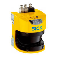
Safety laser scanner
Table of Contents
-
-
-
-
I/O Module16
-
Functions16
-
-
Standby24
-
-
-
Ardous Area24
-
-
-
Design27
-
5 Mounting
50-
Safety50
-
-
-
Safety58
-
-
-
Cds65
-
Application75
-
Resolution75
-
-
Restart76
-
Field Sets78
-
-
Safety92
-
-
-
Disposal105
-
-
-
Data Sheet111
-
General Details111
-
Electric114
-
Optical Fiber116
-
Response Times120
-
14 Spare Parts
124-
Sensor Heads124
-
I/O Modules124
-
-
15 Accessories
125 -
16 Glossary
128 -
17 Annex
131
-
List of Figures
134