beautypg.com
Manuals
Brands
Siemens Manuals
Protection Device
SENTRON 3VL series
Siemens SENTRON 3VL series Manuals
Manuals and User Guides for Siemens SENTRON 3VL series. We have
8
Siemens SENTRON 3VL series manuals available for free PDF download: System Manual, Function Manual, Operating Instructions Manual
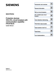
Siemens SENTRON 3VL series System Manual (360 pages)
Switching/protection devices, molded-case circuit breakers
Brand:
Siemens
| Category:
Protection Device
| Size: 16.13 MB
Table of Contents
Table of Contents
5
1 About this Document
11
Introduction
11
2 Product-Specific Information
13
Important Notes
13
3 Product Description
15
SENTRON VL Overview
15
Application Overview
18
Configuration
19
Functional Principle
19
Subdivision According to Power Ranges
19
Thermomagnetic Overcurrent Trip Units
20
Electronic Overcurrent Trip Unit (ETU)
21
Mechanical Operating Mechanisms
23
Toggle Handle Operating Mechanism
23
Rotary Mechanism on Front (Optional)
24
Door-Coupling Rotary Operating Mechanism (Optional)
25
Motorized Operating Mechanisms (Optional)
26
Stored-Energy Motorized Operating Mechanism
27
Motorized Operating Mechanism Without Stored-Energy Mechanism
27
4 System Overview
29
Possible Applications
29
Key Data
30
General Data - 3VL Molded-Case Circuit Breakers
30
General Data - Auxiliary and Alarm Switches
34
General Data - Trip Units
36
General Data - Motorized Operating Mechanisms
38
5 Functions
41
Current Protection
41
Overcurrent Trip Unit
41
Function Overview
44
Setting Options
46
Dimensioning Short-Circuit Protection According to Frame Size
47
General Technical Specifications
48
Differential Current Protection with RCD Module
51
Single-Pole Operation with RCD Module
56
Ground-Fault Protection
58
Voltage Protection
60
Undervoltage Release
60
Shunt Release
62
Auxiliary Switches and Alarm Switches
63
6 Application Planning
65
Use with Frequency Converters
65
Use of Capacitor Banks
67
Primary-Side Transformer Protection
68
Use in DC Systems
69
Use in IT Networks
71
Use in the Motor Protection Area
74
Use in Harsh Environments
78
Use in Series Connection
81
7 Installing/Mounting
83
Installation Methods
83
Mounting and Safety Clearances
87
Locking Devices
91
8 Connecting
97
Cables and Busbars
97
Main Connection Types for Fixed Mounting
107
Main Connection Methods for Plug-In and Withdrawable Version
114
Terminal Assignments
116
Auxiliary Switch Designations
118
Description of the Terminals
118
9 Displays and Operator Controls
121
Overcurrent Trip Unit Without LCD Display
121
Overcurrent Trip Unit with LCD Display
125
Stored-Energy Motorized Operating Mechanism
133
10 Parameter Assignment/Addressing
135
Setting the Parameters
135
Setting the Protection Parameters for Motor Protection (ETU10M, ETU30M and LCD-ETU 40M)
139
11 Service and Maintenance
141
Preventive Measures
141
Troubleshooting
143
12 Technical Data
145
Technical Overview
145
Configuration of Main Connections
150
Switching Capacity Overview
153
Switching Capacity Overview
157
Derating Factors
159
Power Loss
167
Mechanical Operating Mechanisms
170
Motorized Operating Mechanisms
171
Capacitor Banks
173
Motor Protection
174
RCD Modules
177
Undervoltage Release
178
Undervoltage Release Connection Data
180
Shunt Release
182
Shunt Release Connection Data
184
Auxiliary Switches and Alarm Switches
185
Position Signaling Switch
187
Ground Fault Protection Classes
188
IP Degrees of Protection
189
13 Dimensional Drawings
191
VL160X (3VL1), VL160 (3VL2), and VL250 (3VL3), 3- and 4-Pole, to 250 a
191
Circuit Breakers
191
Operating Mechanisms
193
Connections and Phase Barriers
195
Terminal Covers
197
Locking Device for the Toggle Handle
198
Rear Locking Module
198
Accessories
200
Door Cutouts
202
Plug-In Socket and Accessories
204
VL160X (3VL1), 3- and 4-Pole, up to 160 a
206
13.1.10.1 Plug-In Socket and Accessories
206
VL160 (3VL) and VL250 (3VL3), 3- and 4-Pole, up to 250 a
208
13.1.11.1 Withdrawable Version and Accessories
208
VL400 (3VL4), 3- and 4-Pole, up to 400 a
211
Circuit Breaker
211
Operating Mechanisms
212
Connections and Phase Barriers
213
Terminal Covers
215
Rear Interlocking Module
216
Locking Devices, Locking Device for Toggle Handle and Accessories
216
Door Cutouts
219
Plug-In Socket and Accessories
221
VL630 (3VL5), 3- and 4-Pole, up to 630 a
227
Circuit Breaker
227
Operating Mechanisms
228
Connections and Phase Barriers
229
Terminal Covers
230
Rear Interlocking Module
231
Locking and Locking Device for Toggle Handle
232
Accessories
233
Door Cutouts
235
Plug-In Socket and Accessories
237
Withdrawable Version and Accessories
239
VL800 (3VL6), 3- and 4-Pole, up to 800 a
242
Circuit Breaker
242
Operating Mechanisms
243
Withdrawable Version
244
Connections and Phase Barriers
248
Terminal Covers
249
Locking and Locking Device for Toggle Handle
250
Rear Interlocking Module
251
Accessories
252
Door Cutouts
254
VL1250 (3VL7) and VL 1600 (3VL8), 3- and 4-Pole, up to 1600 a
256
Circuit Breaker
256
Operating Mechanisms
258
Withdrawable Version
260
Connections and Phase Barriers
264
Terminal Covers
265
Rear Interlocking Module
268
Locking and Locking Device for Toggle Handle
269
Accessories
269
Door Cutouts
271
Current Transformer
272
VL160X (3VL1) up to VL800 (3VL6), 3- and 4-Pole, up to 800 a
273
Locking with Bowden Wire
273
Busbar Adapter System 8US1
275
VL160X (3VL1) with RCD Block, 3- and 4-Pole, up to 160 a
276
Circuit Breakers
276
Connections and Phase Barriers
277
Terminal Covers
279
Door Cutouts
281
Plug-In Socket and Accessories
283
VL160 (3VL2) and VL250 (3VL3) with RCD Module, 3- and 4-Pole, to 250 a
285
Circuit Breakers
285
Connections and Phase Barriers
286
Terminal Covers
288
Door Cutouts
290
Plug-In Socket and Accessories
292
VL400 (3VL4) with RCD Module, 3- and 4-Pole, up to 400 a
298
Circuit Breakers
298
Connections and Phase Barriers
300
Terminal Covers
302
Door Cutouts
304
Plug-In Socket and Accessories
306
Door-Coupling Rotary Operating Mechanisms 8UC
312
4NC Current Transformers for Measuring Purposes
315
COM20/COM21 (Communications Module for SENTRON 3VL)
316
COM10/COM 11 (Communications Module for SENTRON 3VL)
316
14 Circuit Diagrams
317
15 Spare Parts/Accessories
329
Installation
329
Electromechanical Components
333
Mechanical Components
335
Electrical/Electronic Engineering
337
ESD Guidelines
339
ESD Directive
339
Appendix
341
Selectivity
341
Conversion Tables
344
Standards and Specifications
346
Ordering Data
348
Glossary
351
Siemens SENTRON 3VL series System Manual (318 pages)
IEC molded case circuit breakers
Brand:
Siemens
| Category:
Protection Device
| Size: 13.89 MB
Table of Contents
System Manual, 11/2013, 110 0110 - 02 DS
3
Table of Contents
5
1 About this Document
11
Introduction
11
Technical Support
11
2 Product-Specific Information
13
Important Notes
13
Ordering Data
15
3 Product Description
17
Overview 3VL
17
Application Overview
20
Configuration
22
Functional Principle
22
Subdivision According to Power Ranges
22
Thermal-Magnetic Overcurrent Trip Units
23
Electronic Overcurrent Trip Unit (ETU)
24
Mechanical Operating Mechanisms
26
Toggle Lever Operating Mechanism
26
Rotary Mechanism on Front (Optional)
27
Door-Coupling Rotary Operating Mechanism (Optional)
29
Side Panel Rotary Operating Mechanism (Optional)
30
Motorized Operating Mechanisms (Optional)
32
Motorized Operating Mechanism with Stored Energy Mechanism (SEO)
33
Motorized Operating Mechanism (MO)
34
4 Functions
35
Protection Functions
35
Overcurrent Release
35
Function Overview of the Overcurrent Release
36
Setting Options of the Overcurrent Release
38
General Technical Data of the Overcurrent Release
40
Differential Current Protection with RCD Module
44
Single-Pole Operation with RCD Module
48
Ground-Fault Protection
49
Internal Accessories
51
Possible Complements for the Insulated Accessory Compartments
51
Undervoltage Release
52
Shunt Release
53
Auxiliary Switches and Alarm Switches
54
5 Application Planning
57
Use with Frequency Converters
57
Use of Capacitor Banks
58
Transformer Protection on the Primary Side
59
Use in DC Systems
60
Use in IT Systems
62
Use in Motor Protection
64
Use in Unusual Environments
67
Use in Series Connection
69
Use in Transfer Control System
71
Use in Communication Environment
74
6 Installing/Mounting
77
Installation Methods
77
Mounting and Safety Clearances
80
Locking Devices
84
Locking Devices for a Padlock
84
Locking Device with a Safety Lock
86
Mutual Interlocking of Two Molded Case Circuit Breakers
86
7 Connecting
89
Cables and Busbars
89
Main Connection Types for Fixed Mounting
99
Main Connection Methods for Plug-In and Withdrawable Version
106
8 Displays and Operator Controls
109
Overcurrent Trip Unit Without LCD Display
109
Overcurrent Trip Unit with LCD Display
114
9 Parameter Assignment / Addressing
119
Setting the Parameters
119
Setting the Protection Parameters for Motor Protection (ETU10M, ETU30M and LCD-ETU 40M)
123
10 Service and Maintenance
125
Preventive Measures
125
Troubleshooting
127
11 Technical Data
129
General Data - 3VL Molded Case Circuit Breakers
129
Technical Overview
132
Configuration of Main Connections
136
Derating Factors
142
Use at Altitudes above 2000 Meters
142
Use under Diverse Ambient Temperatures
143
Power Loss
150
Capacitor Banks
152
Motor Protection
153
Motorized Operating Mechanisms
156
RCD Modules
158
Undervoltage Release
159
Time-Delay Device for Undervoltage Releases
160
Shunt Release
161
Auxiliary Switches and Alarm Switches
163
Position Signaling Switch
164
Leading Auxiliary Switches in Front-Operated Rotary Operating Mechanism
166
Ground-Fault Detection
166
IP Degrees of Protection
167
12 Dimensional Drawings
169
VL160X (3VL1), VL160 (3VL2), and VL250 (3VL3), 3- and 4-Pole, to 250 a
169
Molded Case Circuit Breakers
169
Operating Mechanisms
171
Connections and Phase Barriers
174
Terminal Covers
176
Locking Device for the Toggle Lever
177
Rear Interlocking Module
177
Accessories
178
Door Cutouts
179
Plug-In Base and Accessories
181
VL160X (3VL1), 3- and 4-Pole, up to 160 a
183
Plug-In Base and Accessories
183
VL160 (3VL) and VL250 (3VL3), 3- and 4-Pole, up to 250 a
185
Withdrawable Version and Accessories
185
VL400 (3VL4), 3- and 4-Pole, up to 400 a
189
Molded Case Circuit Breakers
189
Operating Mechanisms
190
Connections and Phase Barriers
194
Terminal Covers
195
Rear Interlocking Module
196
Locking Devices, Locking Device for Toggle Lever and Accessories
196
Door Cutouts
198
Plug-In Base and Accessories
200
VL630 (3VL5), 3- and 4-Pole, up to 630 a
206
Molded Case Circuit Breakers
206
Operating Mechanisms
207
Connections and Phase Barriers
210
Terminal Covers
211
Rear Interlocking Module
212
Locking and Locking Device for Toggle Lever
213
Accessories
213
Door Cutouts
214
Plug-In Base and Accessories
216
Withdrawable Version and Accessories
218
VL800 (3VL6), 3- and 4-Pole, up to 800 a
222
Molded Case Circuit Breakers
222
Operating Mechanisms
223
Withdrawable Version
225
Connections and Phase Barriers
230
Terminal Covers
231
Locking and Locking Device for Toggle Lever
232
Rear Interlocking Module
233
Accessories
234
Door Cutouts
235
VL1250 (3VL7) and VL1600 (3VL8), 3- and 4-Pole, up to 1600 a
237
Molded Case Circuit Breakers
237
Operating Mechanisms
238
Withdrawable Version
240
Connections and Phase Barriers
244
Terminal Covers
245
Rear Interlocking Module
248
Locking and Locking Device for Toggle Lever
249
Accessories
249
Door Cutouts
250
Current Transformer
251
12.6 Interlocks for VL160X (3VL1) to VL800 (3VL6), 3- and 4-Pole, up to 800 a
252
Locking with Bowden Wire
252
VL160X (3VL1) with RCD Block, 3- and 4-Pole, up to 160 a
253
Molded Case Circuit Breakers
253
Connections and Phase Barriers
254
Terminal Covers
256
Door Cutouts
257
Plug-In Base and Accessories
260
VL160 (3VL2) and VL250 (3VL3) with RCD Module, 3- and 4-Pole, to 250 a
262
Molded Case Circuit Breakers
262
Connections and Phase Barriers
263
Terminal Covers
265
Door Cutouts
267
Plug-In Base and Accessories
269
VL400 (3VL4) with RCD Module, 3- and 4-Pole, up to 400 a
275
Molded Case Circuit Breakers
275
VL400 (3VL4) Molded Case Circuit Breaker with RCD Front Connection Bar (Connections and Interphase Barriers)
277
Terminal Covers
279
Door Cutouts
281
Plug-In Base and Accessories
283
Door-Coupling Rotary Operating Mechanisms 8UC
288
4NC Current Transformers for Measuring Purposes
291
COM20/COM21 (Communication Module for SENTRON 3VL)
292
13 Circuit Diagrams
293
14 Spare Parts/Accessories
303
Installation
303
Appendix
307
Table of Abbreviations
307
A.1 Table of Abbreviations
307
Standards and Specifications
308
Comprehensive Support from a to Z
310
Index
313
Siemens SENTRON 3VL series System Manual (286 pages)
Circuit breakers with communication capability - PROFIBUS
Brand:
Siemens
| Category:
Circuit breakers
| Size: 4.46 MB
Table of Contents
Table of Contents
3
Introduction and Overview
9
General Information
9
Structure of the Manual
9
Introduction
9
SENTRON Circuit Breakers
9
Bus Systems
11
Profibus Dp
11
Ethernet
14
Modbus RTU
15
Communication Structure of the SENTRON Circuit Breakers
16
General Information
19
Other System Manuals and Literature
19
Approvals
19
Standards and Approvals
20
Orientation Aids
20
Up-To-The-Minute Information at All Times
20
Scope
20
3WL Air Circuit Breakers
23
Introduction and Overview
23
The Cubiclebus
26
Communications Capability of Electronic Trip Units (ETU)
27
Function Overview of the Overcurrent Tripping System
29
Availability of the Data on the Cubiclebus
31
COM15 Module and BSS Module
33
PROFIBUS DP COM15 Module
33
Connection of the COM15 Module
34
PROFIBUS Installation Guideline
37
PROFIBUS Write Protection (Dpwriteenable)
38
Data Exchange Via the COM15
38
Breaker Status Sensor (BSS)
41
Metering Functions
42
Metering Function PLUS
42
Voltage Transformer
48
Delay of the Threshold Warning
53
Functions and Parameters
53
Important Functions and Parameters for Communication
53
Load Management
54
Extended Protection Function
55
Threshold Values
56
Lower Limit of Power Transmission
56
Direction of Incoming Supply
56
Events and Tripping Operations
57
External Cubiclebus Modules
58
General Information
58
Rotary Coding Switch
59
Installing the Cubiclebus Modules
59
Connection of the Power Supply
59
Maximum Configuration of the Cubiclebus
60
Installation Guidelines for the Cubiclebus
61
Connection of External Cubiclebus Modules
61
LED Indicator
64
Test of the Digital Input and Output Modules
65
Digital Input Module
67
Parameter Set Changeover
68
Technical Data
69
Digital Output Module with Rotary Coding Switch
69
Technical Data
71
Configuration of the Digital Output Module
72
LED Indicator
73
Technical Data
76
Analog Output Module
76
Selecting the Measured Values
77
Test Function
81
Technical Data
81
ZSI Module
81
Measuring Accuracy
82
3WL Breaker Measuring Accuracy
82
External Current Consumption with Cubiclebus
83
Power Required by a SENTRON WL with Cubiclebus
83
Selecting the Power Supply
84
3VL Molded-Case Circuit Breaker
87
Brief Description
87
Brief Description of SENTRON VL
87
Overview of the Accessories
88
Properties of the Trip Units
90
Electronic Overcurrent Tripping Systems
90
Protection Functions
90
Data Transfer Via PROFIBUS DP
93
COM20 Connection
95
Data Exchange with the COM20
95
Setting the PROFIBUS Address of the COM20
96
COM20 Pin Assignment
97
PROFIBUS Installation Guidelines COM20
98
PROFIBUS DP Write Protection with COM20
98
Communication Connection to the ETU
99
Connecting the Optional Motorized Operating Mechanism to COM20
99
LED Indicators on the COM20
102
Measuring Accuracy
103
Zone Selective Interlocking
105
Zsi
105
Introduction
105
Selectivity
105
Time Selectivity
106
ZSI Function
107
Operating Principle
108
Course over Time
108
Condition ZSI = on and Presence of a Short-Circuit (S)
108
Condition ZSI = on and Presence of a Ground Fault (G)
109
Examples
110
Function Example
110
Tabular Representation
111
Short-Circuit
111
Ground Fault
111
Example of 3 Grading Levels Without Coupling Switch
112
Cancelation of the ZSI out Signal
113
Coupling Switch
114
Wiring Example
115
Circuit Breakers Without ZSI Function
117
Sentron 3Wl
118
Technical Data
118
Applications
119
Configuration
119
Connection
119
Test Function
119
Led
119
Sentron 3Vl
120
Com20/Com 21
120
Technical Data
120
Applications
121
Configuration
121
Connection
121
Led
121
PROFIBUS Data Transfer
123
Integration of the Circuit Breakers into a Communication System
123
Communication
123
Communication with a PROFIBUS DP Class 1 Master
124
Communication with a PROFIBUS DP Class 2 Master
125
Integration with the GSD File
125
The Three Communication Paths
129
6.7 Setting and Changing the PROFIBUS Address of the COM15/COM20
131
PROFIBUS Profile for SENTRON Circuit Breakers
135
Cyclic Data Traffic
135
Data Transfer to the PLC
143
Interface to S7-300 and Control/Diagnosis Via PROFIBUS
143
Creating a New Project
143
Hardware Configuration in HW Config
146
Interface Setting for Initial Configuration of a CPU Via MPI
152
Control Program Example
154
Procedure for Opening the Programming Tool
154
Using Cyclic Data
155
Read Data Sets
157
Write Data Sets
159
Reading out Diagnostics
160
Sync/Unsync/Freeze/Unfreeze
161
Functional Sequences/Description of Functions
164
Diagnostic Messages
164
SYNC and FREEZE
171
Time Synchronization
172
Data Library
175
Chapter Overview
175
Scaling
176
Abbreviations of the Data Sources
176
Units
177
Function Classes
177
Function Classes of the Data Points
177
Data Points for Controlling the SENTRON Circuit Breakers
178
Data Points for Detailed Diagnostics of the SENTRON Circuit Breakers
179
Data Points for Identifying the SENTRON Circuit Breakers
181
Data Points for Measured Values Current
182
Data Points for Measured Values Voltage
183
Data Points for Measured Values Power
185
Data Points for Other Measured Values
187
Data Points for the Time Stamp (TS) of the Measured Values
189
Parameters of the SENTRON Circuit Breakers (Primary Protection Function)
191
Parameters of the SENTRON Circuit Breakers (Extended Protection Function)
193
Parameters of the SENTRON Circuit Breakers (Parameters for Threshold Value Alarms)
195
Parameters of the SENTRON Circuit Breakers
198
Adjustment, Etc.)
198
Data Sets
199
Data Set DS 0 S7-V1 System Diagnostics
199
Data Set DS 1 System Diagnostics
200
Data Set DS 51 Main Overview
201
Data Set DS 52 Main Overview 1
203
Data Set DS 64 Data of the Harmonic Analysis
206
Data Set DS 68 Data of the Cubiclebus Module
207
Data Set DS 69 Status of the Modules
208
Data Set DS 72 Min. and Max. Measured Values
210
Data Set DS 73 Min. and Max. Measured Values of the Voltages
214
Data Set DS 74 Min. and Max. Measured Values of the Powers
217
Data Set DS 76 Min. and Max. Measured Values of the Frequency and the THD
219
Data Set DS 77 Min. and Max. Measured Values of the Temperatures
221
Data Set DS 91 Statistical Information
222
Data Set DS 92 Diagnostics Data
224
Data Set DS 93 Controlling the Circuit Breakers
226
Data Set DS 94 Current Measured Values
227
Data Set DS 97 Detailed Identification
232
Data Set DS 100 Identification Overview
234
Data Set DS 128 Parameters of the Metering Function and Extended Protection Function
235
Data Set DS 129 Parameters of the Protection Function and Settings for Load Shedding and Load Pick up
239
Data Set DS 130 Parameters for the Threshold Values
243
Data Set DS 131 Switching the Parameters for the Extended Protection Function and the Threshold Values on and off
248
Data Set DS 160 Parameters for Communication
251
Data Set DS 162 Device Configuration
252
Data Set DS 165 Identification Comment
253
Formats
253
Formats of the Data Points
253
General Data Formats
254
Special Data Formats
257
Data Formats 15 to 24
259
Data Formats 88 to 162
264
Data Formats 307 to 373
270
Data Formats 401 to 426
275
List of Abbreviations
279
Glossary
281
Index
285
Siemens SENTRON 3VL series Function Manual (146 pages)
for SIMATIC PCS 7
Brand:
Siemens
| Category:
Power Tool
| Size: 3.91 MB
Table of Contents
A5E02316914A
3
Table of Contents
5
1 Introduction
9
General
9
Further Documentation
9
Installing the Library
9
Simatic Pcs
9
Hardware Configuration
10
Incorporating Via GSD File
10
Figure 1-1 Catalog Path for Incorporating Via GSD File
10
Figure 1-2 Selection of Basic Type for 3WL
10
Figure 1-3 Selection of Basic Type for 3VL
11
Figure 1-4 Properties of the 3WL / 3VL Device Directly Connected to the DP Master System
12
Figure 1-5 Properties of the 3WL / 3VL Device Following a y Link
13
2 Information about the Library
15
Overview of the Blocks
15
General Information about os Typicals
15
Faceplates
15
Figure 2-1 Section of the Overview Display
15
Figure 2-2 Trend Setting on the Icon
16
Symbols
17
Figure 2-3 Icons in Graphics Designer
17
3 Description of Blocks
19
Diagnostics Block DIA_WLVL
19
Calling Obs
20
Called Blocks
20
Function
20
Message Behavior
20
Error Behavior
21
I/O Access Error
21
Module Fault
21
Read Diagnostics Data of 3WL / 3VL
21
Start-Up Characteristics
22
Block Parameters
22
3.2 Driver Module DRV_3WL
24
Calling Obs
24
Called Blocks
25
Function
25
Message Behavior
28
Assignment of the Cyclic Process Image
29
Addressing and Module Driver
30
Processing the Diagnostics Data of the 3WL Device
30
Start-Up Characteristics
31
Block Parameters
31
Description of Symbols and Faceplates
62
Figure 3-1 Symbol with 1 Measurement
63
Figure 3-2 Faceplate for Standard View
65
Figure 3-3 Faceplate for Measurements View, Current Tab
67
Figure 3-4 Faceplate for Measurements View, Voltage Tab
68
Figure 3-5 Faceplate for Measurements View, Active Power/Energy Tab
69
Figure 3-6 Faceplate for Measurements View, Reactive Power/Energy Tab
70
Figure 3-7 Faceplate for Measurements View, Apparent Power Tab
71
Figure 3-8 Faceplate for Measurements View, Miscellaneous Tab
72
Figure 3-9 Faceplate for Diagnosis View, Warnings Tab
73
Figure 3-10 Faceplate for Diagnosis View, Trip Reason Tab
74
Figure 3-11 Faceplate for Diagnosis View, Setpoints Tab
76
Figure 3-12 Faceplate for Maintenance View, Maintenance 1 Tab
78
Driver Module DRV_3VL
97
Calling Obs
98
Called Blocks
98
Function
98
Message Behavior
101
Assignment of the Cyclic Process Image
102
Addressing and Module Driver
103
Processing the Diagnostics Data of the 3VL Device
104
Start-Up Characteristics
104
Block Parameters
104
Description of Symbols and Faceplates
113
4 Configuration Manual
127
Interconnections on COM15 for 3WL
127
DC Voltage
128
Other Voltage Levels
129
Interconnections on COM10 for 3VL
130
Connection for Communication
130
Connection for Motorized Operating Mechanism
131
Connection on COM20 for 3VL
132
COM20 Pin Assignment
132
Connecting the Optional Motorized Operating Mechanism to COM20
133
Configuring a Measuring Point
134
Creating the PLC Program
134
Figure 4-9 Driver Block in CFC Chart Connected
136
Connection to Wincc
137
Figure 4-11 Creating Block Icons out of Plant Hierarchy
138
5 Technical Specifications
141
6 Technical Support
143
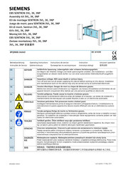
Siemens SENTRON 3VL series Operating Instructions Manual (12 pages)
Assembly kit
Brand:
Siemens
| Category:
Racks & Stands
| Size: 1.72 MB
Siemens SENTRON 3VL series Operating Instructions Manual (10 pages)
Assembly kit
Brand:
Siemens
| Category:
Racks & Stands
| Size: 1.65 MB
Siemens SENTRON 3VL series Operating Instructions Manual (10 pages)
Assembly kit withdrawable design
Brand:
Siemens
| Category:
Racks & Stands
| Size: 1.39 MB
Siemens SENTRON 3VL series Operating Instructions Manual (10 pages)
Assembly kit
Brand:
Siemens
| Category:
Racks & Stands
| Size: 1.07 MB
Related Products
Siemens SENTRON 3VL160
Siemens SENTRON 3VL160X
Siemens SENTRON 3VL250
Siemens SENTRON 3VL400
Siemens SENTRON 3VL630
Siemens SENTRON 3VL800
Siemens SENTRON 3VL1250
Siemens SENTRON 3VL1600
Siemens SIRIUS 3RB3
Siemens SENTRON 3WA
Siemens Categories
Industrial Equipment
Controller
Control Unit
Oven
Washer
More Siemens Manuals