beautypg.com
Manuals
Brands
Siemens Manuals
Other
Siprotec 7VK61
Siemens Siprotec 7VK61 Manuals
Manuals and User Guides for Siemens Siprotec 7VK61. We have
2
Siemens Siprotec 7VK61 manuals available for free PDF download: Manual
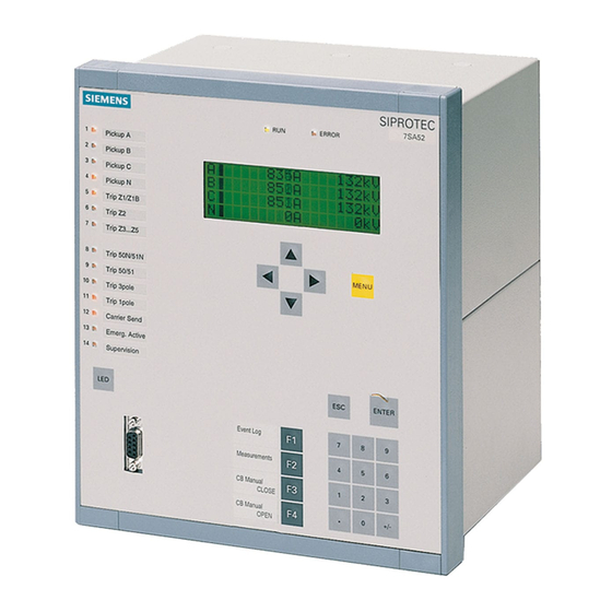
Siemens Siprotec 7VK61 Manual (332 pages)
Breaker Management Device
Brand:
Siemens
| Category:
Other
| Size: 5.4 MB
Table of Contents
C53000-G1176-C159
3
Table of Contents
9
1 Introduction
15
Overall Operation
16
Application Scope
18
Characteristics
20
2 Functions
23
General
24
Functional Scope
24
Configuration of the Scope of Functions
24
Setting Notes
24
Settings
26
Device
27
Trip-Dependent Indications
27
Setting Notes
27
Settings
28
Information List
28
Power System Data 1
30
Setting Notes
30
Settings
34
Change Group
35
Purpose of the Setting Groups
35
Setting Notes
35
Settings
36
Information List
36
Power System Data 2
36
Setting Notes
36
Settings
38
Information List
38
Oscillographic Fault Records
40
Description
40
Setting Notes
40
Settings
41
Information List
41
Ethernet EN100-Module
42
Function Description
42
Setting Notes
42
Information List
42
Automatic Reclosure Function (Optional)
43
Function Description
43
Setting Notes
55
Settings
62
Information List
65
Overcurrent Protection (Optional)
67
General
67
Functional Description
67
Setting Notes
73
Settings
78
Information List
80
Synchronism and Voltage Check (Optional)
81
Functional Description
81
Setting Notes
87
Settings
93
Information List
94
Under and Over-Voltage Protection (Optional)
96
Overvoltage Protection
96
Undervoltage Protection
102
Setting Notes
106
Settings
109
Information List
111
Circuit Breaker Failure Protection (Optional)
114
Method of Operation
114
Setting Notes
126
Settings
129
Information List
130
Monitoring Function
131
Measurement Supervision
131
Hardware Monitoring
131
Software Monitoring
133
Monitoring External Transformer Circuits
133
Monitoring the Phase Angle of the Positive Sequence Power
138
Malfunction Reaction
141
Setting Notes
143
Settings
144
Information List
145
Trip Circuit Supervision
145
Functional Description
145
Setting Notes
148
Settings
149
Information List
149
Function Control
150
General
150
Line Energisation Recognition
150
Detection of the Circuit Breaker Position
152
Open Pole Detector
154
Pickup Logic of the Entire Device
156
Tripping Logic of the Entire Device
157
Setting Notes
161
Circuit Breaker Trip Test
161
Functional Description
161
Information List
162
Auxiliary Functions
163
Message Processing
163
Method of Operation
163
Statistics
166
Function Description
166
Setting Notes
167
Information List
167
Measurement
167
Functional Description
167
Information List
169
Energy
170
Energy Metering
170
Setting Notes
170
Information List
170
Command Processing
171
Control Authorization
171
Type of Commands
171
Sequence in the Command Path
172
Interlocking
173
Information List
175
Control Device
175
Description
176
Information List
176
Process Data
177
Method of Operation
177
Information List
178
Protocol
178
3 Mounting and Commissioning
179
Mounting and Connections
180
Configuration Information
180
Hardware Modifications
184
General
184
Disassembly
186
Switching Elements on Printed Circuit Boards
188
Interface Modules
199
Reassembly
202
Mounting
203
Panel Flush Mounting
203
Rack and Cubicle Mounting
204
Panel Mounting
206
Checking Connections
207
Checking Data Connections of Serial Interfaces
207
Checking the System Connections
210
Commissioning
212
Test Mode / Transmission Block
213
Test Time Synchronisation Interface
213
Testing the System Interface
214
Checking the Switching States of the Binary Inputs/Outputs
216
Checking for Breaker Failure Protection
218
Current, Voltage, and Phase Rotation Testing
220
Directional Check with Load Current
221
Polarity Check for the Voltage Input U
222
Polarity Check for the Current Input I
224
Measuring the Operating Time of the Circuit Breaker
224
Check of the Signal Transmission for Breaker Failure Protection And/Or End Fault Protection
225
Testing User-Defined Functions
225
Trip and Close Test with the Circuit Breaker
225
Switching Test of the Configured Operating Equipment
226
Triggering Oscillographic Recording for Test
226
Final Preparation of the Device
228
4 Technical Data
229
General
230
Analogue Inputs and Outputs
230
Auxiliary Voltage
230
Binary Inputs and Outputs
231
Communication Interfaces
232
Electrical Tests
236
Mechanical Tests
237
Climatic Stress Tests
238
Deployment Conditions
239
Construction
239
Automatic Reclosure (Optional)
240
Time Overcurrent Protection
241
Synchronism and Voltage Check (Optional)
248
Voltage Protection (Optional)
250
Circuit Breaker Failure Protection (Optional)
253
Monitoring Functions
254
User Defined Functions (CFC)
256
Auxiliary Functions
260
Dimensions
262
Panel Flush Mounting or Cubicle Mounting (Housing Size 1 / 3 )
262
Panel Flush Mounting or Cubicle Installation (Housing Size / )
263
Panel Surface Mounting (Housing Size 1 / 3 )
264
Panel Surface Mounting (Housing Size )
264
Appendix
265
Ordering Information and Accessories
266
Ordering Information
266
Ordering Code (MLFB)
266
Accessories
268
A.1.2 Accessories
268
Terminal Assignments
271
Housing for Panel Flush or Cubicle Mounting
271
A.2 Terminal Assignments
271
Housing for Panel Surface Mounting
273
Connection Examples
275
Current Transformer Connection Examples
275
A.3 Connection Examples
275
Voltage Transformer Connection Examples
276
Default Settings
279
Leds
279
Binary Input
279
A.4 Default Settings
279
Binary Output
281
Function Keys
281
A.4.3 Binary Output
281
Default Display
282
A.4.5 Default Display
282
Pre-Defined CFC Charts
283
Protocol-Dependent Functions
284
Functional Scope
285
A.6 Functional Scope
285
Settings
286
A.7 Settings
286
Information List
294
A.8 Information List
294
Group Alarms
312
A.9 Group Alarms
312
Measured Values
313
A.10 Measured Values
313
Literature
315
Glossary
317
Index
329
Siemens Siprotec 7VK61 Manual (94 pages)
Input/Output unit, Bay control unit, Communication module, PROFIBUS-DP Communication profile
Brand:
Siemens
| Category:
Protection Device
| Size: 0.65 MB
Table of Contents
Preface
3
Revision Index
7
Table of Contents
9
1 PROFIBUS Communication Modules
11
Communication Module Types and Hardware Revisions
12
Communication Module Types
12
Hardware Revisions
12
Compatibility of the Communication Module Hardware with PROFIBUS-DP Firmware Versions and Mapping Files
13
Display of Module-Specific Information at the SIPROTEC Device
15
Block 1: Status and Parameters of the PROFIBUS-DP Slave
17
Block 2: Firmware Versions and Mapping File
19
Block 3: Module Hardware Information and Boot Firmware Version
20
Block 4: OLM Information
21
Block 5: Status of the Event List Via PROFIBUS-DP
24
2 Parameters and Properties
25
Bus Specific Parameters
26
PROFIBUS-DP Settings
26
Configuration of the Fibre-Optical Interface
28
Event List Settings
31
PROFIBUS-DP Configuration Data
31
Execution of Switching Operations Via PROFIBUS-DP
32
Command Output Modes
32
Transformer Tap Change Commands
33
Behaviour under Special Operating Conditions
33
Response in the Event of Disturbed Communication to the PROFIBUS-DP Master
34
Communication Interruption
34
Signalling of Line-Breaks in a Redundant Fibre-Optical Ring
35
Annunciations to the PROFIBUS-DP Master
37
Event List Via PROFIBUS-DP (Sequence of Events Recorder)
38
Properties of the Event List
39
Structure of a PROFIBUS-DP Telegram with Event List
40
Telegram in Input Direction
40
Telegram in Output Direction
42
Handshake Mechanism
43
3 Data Type Definitions
45
Single-Point Indication (SP, Input)
46
Single Command (SC, Output)
47
Double-Point Indication (DP, Input) / Double Command (DC, Output)
48
Measured Value (Signed Integer)
49
Measured Value (Float)
50
Metered Measurand (Unsigned Long)
51
Transformer Tap Change Command (TC)
52
Transformer Tap Position Indication (TM)
53
Message Block for Event List Via PROFIBUS-DP
54
4 PROFIBUS-DP - Parameterization in DIGSI
57
Interface Selection and Mapping Files
58
Standard Mappings 3-1 to 3-N
58
Compatibility with Standard Mappings of Previous Versions
59
Interface Selection and Mapping Selection in DIGSI 4.21
59
Interface Selection and Mapping Selection in DIGSI 4.3 or Higher
63
Customization of the Allocations
66
Scaling of Measured Values
70
Measurement Conversion
70
Number Representation Depending on the Parameterization
71
Parameterization in DIGSI
73
Time Synchronization
75
PROFIBUS-DP Master
75
Parameterization in DIGSI
77
Using SFC14 and SFC15 in STEP7
79
5 Technical Data
83
Connection Via the PSE Module
84
Connection Via the PSO Module
86
Glossary
89
Index
91
Related Products
Siemens 7VK512
Siemens SIPROTEC 7VE63
Siemens SIPROTEC 7VU681
Siemens SICROWBAR 7VV3003
Siemens 7VV3003-8TA74
Siemens 7VV3003-5CG32
Siemens 7VV3003-5DG32
Siemens 7VV3003-5GG32
Siemens 7VV3003-5JG32
Siemens 7VV3003-5MG32
Siemens Categories
Industrial Equipment
Controller
Control Unit
Oven
Washer
More Siemens Manuals