beautypg.com
Manuals
Brands
Tadiran Telecom Manuals
Computer Hardware
Coral IPx Office
Tadiran Telecom Coral IPx Office Manuals
Manuals and User Guides for Tadiran Telecom Coral IPx Office. We have
1
Tadiran Telecom Coral IPx Office manual available for free PDF download: Installation And Hardware Reference Manual
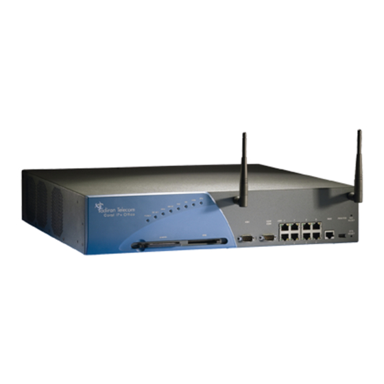
Tadiran Telecom Coral IPx Office Installation And Hardware Reference Manual (510 pages)
Brand:
Tadiran Telecom
| Category:
Computer Hardware
| Size: 10.66 MB
Table of Contents
Table of Contents
11
Chapter 1: Introduction
27
About this Manual
29
Document Description
29
Related Documentation
31
Special Symbols Used in this Document
33
List of Acronyms
34
About the Coral Ipx Office
37
System Description
37
Table 1-2 Ipx Office System Specifications
40
Recommended Tools
41
Chapter 2: Hardware Installation Procedure
43
Site Inspection
45
Installation Environment
45
Space Requirements
46
Table 2-1 Coral Ipx Office Dimensions
47
Table 2-3 Coral Ipx Office Space Requirements
47
Figure 2-1 Coral Ipx Office Main Unit Sizes
48
Figure 2-2 Coral Ipx Office Expansion Unit Sizes and Weights
48
Figure 2-3 Coral Ipx Office Space Requirements (from Side Panels)
48
Figure 2-4 Coral Ipx Office Space Requirements (from Front and Rear Panels)
49
Electrical Requirements
50
Table 2-4 Coral Ipx Office Maximum Power Requirements
51
Equipment Installation
53
Introduction
53
Unpacking the Shipping Container
54
Figure 11-3: NTU Office Card
55
Table 2-5: Part List (Items Per Ipx Office Main Unit)
55
Table 2-6: Part List (Items Per Ipx Office Expansion Unit)
56
Preparing the Unit for Installation
57
Installing the Front Section Cards
58
Installing the External Components
58
Mounting the Ipx Office Onto a Table
59
Figure 2-5 Table Mounting Bumpers
59
Figure 2-6 Ipx Office Unit Mounted on Table
59
Mounting the Office Onto a Rack
60
Figure 2-7 23" Bracket Installation
60
Figure 2-8 Ipx Office Unit Mounted Onto Rack
61
Figure 2-9 Removing Ipx Office Unit from Rack
63
Ground Wiring
64
Figure 2-10 Coral Ipx Office Cage Ground Assembly
65
Figure 2-11 Master Ground Unit
66
Figure 2-12 Main System Ground Connection
67
Figure 2-13 System Ground Connection with Main and Two Expansion Units
68
Strapping the Configuration Jumpers
69
10 Peripheral Card Installation
70
Figure 2-14 ESD Strap Connection to Cage
70
Table 2-7 Coral Ipx Office Card Types
74
Figure 2-15 Coral Ipx Office Main Unit Card Placement
75
Figure 2-16 Coral Ipx Office 1St Expansion Unit Card Placement
75
Figure 2-17 Coral Ipx Office 2Nd Expansion Unit Card Placement
75
Figure 2-18 1St Expansion Cage Ipx 500X Card Placement
76
Figure 2-19 2Nd Expansion Cage Ipx 500X Card Placement
77
Figure 2-20 1St Expansion Cage Ipx 800X Card Placement
78
Figure 2-21 2Nd Expansion Cage Ipx 800X Card Placement
79
Figure 2-22 System with One Flexicom 200 Expansion Unit
80
Figure 2-23 1St Flexicom 200 Cabinet in a System with Two Expansion Cabinets
81
Figure 2-24 2Nd Flexicom 200 Cabinet in a System with Two Expansion Cabinets
82
11 Interconnecting Ipx Office Main and the Expansion Units
83
12 Installing the DC Power Supply
87
Figure 2-25: PS Office DC Front Panel
88
13 Connecting the Power Wires
89
Figure 2-26 AC Power Connection for One Ipx Office Unit
89
Figure 2-27 AC Power Connection for Three Ipx Office Units
90
Figure 2-28 DC Power Wiring for One Ipx Office Unit
92
Figure 2-29 DC Power Wiring for Three Units
92
Program Interface Device Connection
93
Figure 2-30 9-Pin Program Interface Device Connections to KB0
94
Chapter 3: Initial Power-Up Tests
97
Power Supply Test
97
AC Powered Systems
97
Figure 3-1 Coral Ipx Office Unit AC Power Connections
98
DC Powered Systems
99
Figure 3-2 Ipx Office Unit DC Power Connections
100
Common Control Test
101
Activating and Initializing the Control Card
101
Memory Lithium Battery Condition Test
105
Identifying the Coral Expansion Units
107
Introduction
107
Coral Ipx Office Software Version 15
107
Table 3-1 Minimum Software Version Per Expansion Unit Type
107
Coral Ipx Office Software Version 15.5 or Higher
108
Peripheral Interface Card Initialization
109
Introduction
109
Table 3-2: Card Slot Status Messages
113
System Initialization
114
I/O Cable Installation
117
Figure 3-3: Velcrotm Strap on Champtm Connector
117
Figure 3-4 MDF Connector Configuration
118
Completing the Installation
119
Chapter 4: Software Installation Procedure
121
Generic Feature Software
123
Introduction
123
Upgrading Using the Fmprog-Utility
124
Installing an Upgraded IMC8 Card
125
Upgrading the Embedded Application Software
127
System Database Control
129
Accessing the Database Flash Menu
129
Saving to IMC8
130
Loading (Restoring) from IMC8
132
Show File Information
134
Automatic Daily Backup
135
Erasing Flash Memory
136
Chapter 5: External Connections
139
Main Distribution Frame (MDF)
139
General
139
Table 5-1: External I/O Connectors for Coral Ipx Office Peripheral Cards
141
Figure 5-1 Connecting Via an MDF
142
Figure 5-2: Twisted Pair TIP and Ring Wiring Detail
143
External Equipment
145
Station Equipment
145
Table 5-2 Station Interface Wire Pair Requirements
146
Figure 5-3 Modular Wired Station Jack Wiring Diagram
147
Trunk Circuits
149
Figure 5-4 Typical Trunk Circuit Wiring Diagram
149
Auxiliary Connections
150
Protection Devices
151
Introduction to Primary and Secondary Protection Devices
151
Table 5-4: Telephone Circuit Primary Protection Device Specifications
152
Table 5-5 Telephone Circuit Secondary Protection Device Specifications
153
Surge Arrestor Magazine
154
Figure 5-5 Magazine with 10 Surge Arrestor and Voltage Protector Units
154
Power Fail (PF) Transfer Circuits
155
Physical Connection
155
Database Programming
156
Figure 5-6 Power Fail Wiring to Single-Line Telephone Set
156
Data Communication Ports
157
Figure 5-7: Flexset 80 / 280S / 281S / APDL / APA or PEX+APA RS-232E (V.24) Pinout
158
Peripheral Cards Index
159
I/O Card Connections
159
Champ Connections
163
Table 5-7 Peripheral Card Connection Information
163
Figure 5-8 4S Office and 8S Office Jumper Settings
163
Table 5-8: Champ 50 Connector Card Pinout (4/8/20S 4/8/16/24SA)
164
Table 5-9: Champ 50 Connector Card Pinout (8/16/24SFT)
165
Table 5-10: Champ 50 Connector Card Pinout (4Sa+8Fx, 4Sa+16Fx, 8Sa+8Fx, 8Sa+16Fx, 4S+8Fx 4S+16Fx, 8S+8Fx, 8S+16Fx)
166
Table 5-11: Block 66 MDF Pinout (4/8/16/24SA, 4/8/20S)
167
Table 5-12: Block 66 MDF Pinout (8/16/24SFT)
168
Table 5-13: Block 66 MDF Pinout (4Sa+8Fx, 4Sa+16Fx, 8Sa+8Fx, 8Sa+16Fx, 4S+8Fx, 4S+16Fx 8S+8Fx, 8S+16Fx)
169
Connections
170
Table 5-14 4T / 4T-CID Office Pinout
171
Figure 5-9 4T / 4T-CID Office Pinout
171
Figure 5-10 8T / 8T-CID Office Pinout
172
Table 5-15: 8T / 8T-CID Office Pinout
172
Table 5-16 4TBR Office Pinout - for All Connectors
173
Figure 5-11 4TBR Office Pinout
173
Table 5-17 UDT Office (T1 or PRI-23) Pinout
174
Figure 5-12 UDT Office (T1 or PRI-23) Pinout
174
Table 5-18: PRI-30 Office Pinout
175
Table 5-19 30T Office Pinout (30T or 30TM)
176
Figure 5-14 30T Office Pinout (30T or 30TM)
176
LAN, WAN, and Printer Connections
177
Figure 5-15 Network Connection When an NTU Office Card Is Not Supplied
177
Figure 5-16 Network Connection When an NTU Office Card Is Supplied
177
Connecting to the LAN
178
Connecting to the WAN
178
Connecting to a Printer
179
LAN/WAN Pinout
180
Chapter 6: System Description
181
General System Description
183
Exterior Housing
183
Figure 6-1 Front View of the Table-Mounted Ipx Office Unit
184
Figure 6-2 Front View of the Rack-Mounted Ipx Office Unit
184
Figure 6-3 Main Unit Front Panel
185
Figure 6-4 Expansion Unit Front Panel
185
Table 6-1 Front Panel Features
186
Rear Side
187
Figure 6-5 Rear Side of the Ipx Office Unit
188
Figure 6-6 Left Panel of the Ipx Office Main Unit
189
Figure 6-7 Right Panel of the Ipx Office Main Unit
189
Unit Cover
190
Figure 6-8 Left View of the Ipx Office Main Unit Cover
190
Figure 6-9 Left View of the Ipx Office Expansion Unit Cover
190
Figure 6-10 Removing the Unit Cover
191
Figure 6-11 Closing the Cover
192
Unit Interior
193
Figure 6-12 Ipx Office Main Unit Interior
193
Figure 6-13 Ipx Office Expansion Unit Interior
195
Rear Section
196
Figure 6-14 Ipx Office Rear Section Without Cards Installed
196
Table 6-2 Blank Panel Description
198
Figure 6-16 Ipx Office with Blank Panels
199
Heat Removal
200
Cooling Fans
201
Figure 6-18 Fan Dismounting
202
Figure 6-19 Fan Installation
203
Safety Labels
204
Figure 6-21 Electrical Hazard Label
205
Figure 6-22 ESD and Ground Labels
206
System Configuration Options
207
General Description
207
Table 6-3 Ipx Office System Configuration Options
207
Table 6-4 Number of Universal I/O Slots Per System Configuration
209
Figure 6-23 System with One Unit (Ipx Office)
209
Figure 6-24 System with Ipx Office Main Unit and One Ipx Office Expansion Unit
210
Figure 6-25 System with Ipx Office Main Unit and Two Ipx Office Expansion Units
210
Figure 6-26 System with Two Units (Ipx Office and Ipx 500X)
211
Figure 6-27 System with Three Units (Ipx Office and Two Ipx 500X Cages)
212
Figure 6-28 System with Two Units Ipx Office and Ipx 800X)
213
Figure 6-29 System with Three Units (Ipx Office, Ipx 500X, and Ipx 800X)
214
Figure 6-30 System with Three Units (Ipx Office and Two Ipx 800X Cages)
215
Figure 6-31: System with Two Units (Ipx Office and One Flexicom 200 Cabinet)
216
Figure 6-32: System with Three Units (Ipx Office and Two Flexicom 200 Cabinets)
216
Ipx Office and Ipx Expansion Unit Installation Configurations
217
Table 6-5 Ipx Office System Expansion Options
217
Figure 6-33 Connection between Two Units
219
Figure 6-34 Connection between Three Units
219
Figure 6-35 Connection between the Ipx Office and 500X
219
Figure 6-36 Connection between the Ipx Office Unit and Two 500X
220
Figure 6-37 Connection between the Ipx Office Unit and the 800X Cage
220
Figure 6-38 Connection between the Ipx Office Unit, 500X and 800X Cages
221
Figure 6-39: Connection between the Ipx Office Unit and Two 800X Cages
222
Figure 6-40 Connection between the Ipx Office Unit and One Flexicom 200 Cabinet
223
Figure 6-41 Connection between the Ipx Office Unit and Two Flexicom 200 Cabinets
224
Suggestions for Peripheral Card Distribution
225
Table 6-6 Timeslot Distribution in Coral Ipx Office Main Unit
225
Table 6-7 Timeslot Distribution in Coral Ipx Office Expansion Unit
226
Figure 6-42 PCM Timeslot Distribution with Ipx Office Expansion Units Installed
226
Table 6-8 Timeslot Distribution in Ipx 500/800 Expansion Cages
227
Figure 6-43 PCM Timeslot Distribution with Ipx 500X/800X Cages Installed
228
Table 6-9 Timeslot Distribution in Ipx 500/800 Expansion Cages
229
Figure 6-44 PCM Timeslot Distribution with Flexicom 200 CSLX Cabinets Installed
229
Optional Coral Ipx 800X Expansion Cage
230
Chapter 7: Power Supply
233
PS Office AC Power Supply Unit
235
General Description
235
Figure 7-1 PS Office AC Front Panel
236
Figure 7-2 PS Office AC Card Layout
237
Figure 7-3 PS Office AC Card Rear View
237
Circuit Description
238
Installation and Activation
240
Figure 7-5: Ipx Office AC Power Connections
242
Troubleshooting
243
Replacing the PS Office AC Fuses
244
Specifications
246
PS Office DC Power Supply Unit
247
General Description
247
Figure 7-6 PS Office DC Front Panel
248
Figure 7-7 PS Office DC Card Layout
249
Figure 7-8 DC Power Supply Rear View
249
Circuit Description
250
Figure 7-9 PS Office DC Block Diagram
251
Installation and Activation
252
Figure 7-10 PS Office DC Connection
254
Troubleshooting
256
Replacing the PS Office DC Power Fuse
256
Specifications
257
Chapter 8: Common Control Cards
261
Control Cards
261
Figure 8-1 MCB Office Card Layout
263
Card Handling Procedures
264
MCB Office Card
265
General Information
265
Card Components
265
Figure 8-2 MCB Office Card Layout
267
Main Control Processor
268
Universal Gateway
269
Group Controller Circuit
270
Figure 8-3 Coral Ipx Office Voice Switching
271
Figure 8-4 Highways for Ipx Office with Ipx Expansion Units
272
Figure 8-5 Highways for Ipx Office with Ipx 500X/800X Cages
273
Figure 8-6 Highways for Ipx Office with Flexicom 200 CSLX Cabinets
274
Software Authorization Management
276
Figure 8-7 Software Authorization Unit (SAU) Detail
277
Front Panel Features
278
IMC8 Flash Memory Card
279
KB0 RS-232E Programming Port
280
Table 8-1 KB0 RS-232E Interface Pin Functions
280
Figure 8-8 KB0 Pin Assignment
280
UGW RS-232E Programming Port
281
Table 8-2 UGW RS-232E Interface Pin Functions
281
Figure 8-9 UGW Pin Assignment
281
Installing the DBM Memory Card
282
Lithium Battery Condition Testing
283
Figure 8-10 MCB Office Card Battery Insulator Release
284
Specifications - MCB Office
285
LED Card
287
General Information
287
Figure 8-11 LED Office Card
287
Replacing the LED Office Card
288
MRC Card
289
General Information
289
Table 8-3: Coral Ipx Office Main Unit Number of IP Endpoints
290
Figure 8-13: MRC Card Layout - Bottom View
291
Installing the MRC
292
Figure 8-14 MRC Assembly Onto MCB Office
293
Removing the MRC
294
IMC8 Flash Memory Card
295
General Information
295
Figure 8-15 IMC8 Flash Memory Card - Left Side
295
Removing the IMC8
296
Inserting the IMC8
298
Specifications
300
Compact Flash Disk
301
Introduction
301
Inserting the CFD
301
Removing the CFD
301
Figure 8-16 CFD Card
301
DBM Card
303
General Information
303
Figure 8-17 DBM-X Card Layout
303
Installing the DBM Card
305
Table 8-5 Assembly Parts Used in DBM Card Assembly Kit
305
Figure 8-18 DBM Assembly Onto MCB Office
307
Removing the DBM Card
308
Specifications - DBM Card
309
Chapter 9 : Shared Service Cards
313
Shared Service Circuitry
313
General Description
313
Shared Service Cards in the Main Unit
313
Card Handling Procedures
313
MRC Cards
313
U-RMI, U-MR, RMI and MR Office Cards
314
Shared Service Features in the Main Unit
314
Additional Shared Service Cards in the Expansion Cages
315
MRC-8, 16, 32, 64 Modules
317
General Description
317
Layout and Installation
318
Figure 9-1 MRC Card Layout
318
U-RMI / U-MR / RMI / MR Office Cards
319
General Description
319
Table 9-3 U-RMI / U-MR / RMI / MR Office Card List (Route: CLIS)
319
Features
320
Figure 9-2 U-RMI / U-MR / RMI MR Office Architecture
321
Figure 9-3 U-RMI Office Card Circuits Layout, Front Panel and Jumpers
323
Figure 9-4 RMI Office Card Circuits Layout, Front Panel and Jumpers
324
Figure 9-5 U-MR Office Card Circuits Layout, Front Panel and Jumpers
325
Figure 9-6 MR Office Card Circuits Layout, Front Panel and Jumpers
326
Configuration Jumpers
327
Indicators
328
Table 9-6 Card LED Indications
328
Figure 9-7 Card LED Indications
328
External Connectors
329
Table 9-7 External Connections
329
Figure 9-8 External Connections (Front View)
329
Figure 9-9 Music and Paging Plugs Connection
329
Mr/Rmi-F Eprom (U60)
330
Figure 9-10: MR/RMI-F Features
330
Table 9-9 MR and RMI-F PI (Route: PLIS)
332
Urc Prom (U73)
333
Table 9-11 PI Defaults Per URC2 Resource
334
Table 9-12: URC2 Features
336
Table 9-13 URC DTR/DTMF PI Configuration
337
Table 9-14 URC DTB PI Route
339
Table 9-15 URC Spare Ports (Not Used)
339
Table 9-16 URC Three-Way Conference (C3WAY) PI Configuration
340
Table 9-17: URC Idsp CID (Caller ID) Transmitters PI Configuration
341
Table 9-18 URC Dial Tone Detector (DTD) PI Configuration
343
Three-Way Conference (3-Way)
345
General Description
345
Database Programming
346
Additional 3-Way Circuits
347
Specifications - 3-Way Conference
348
Multi-Party Conference (CONF)
349
General Description
349
Feature Descriptions
350
Database Programming
351
Additional Multi-Party Conference Circuits
354
Specifications - Multi-Party Conference
355
DTMF Receiver (DTR)
357
General Description
357
How Many DTMF Receiver Circuits (Dtrs) Are Required
358
Additional DTR Circuits
358
Database Programming
359
Specifications - DTR
360
Dial Tone Detector (DTD)
361
General Description
361
Database Programming
362
Additional DTD Circuits
363
Specifications - DTD
364
Caller ID for SLT (Idsp)
365
General Description
365
Database Programming
366
Additional CID Circuits
367
Specifications - CID
368
MFC Receiver (MFR)
369
General Description
369
Available MFR Circuits
369
Specifications
370
Voip Media Gateway (MG)
371
General Description
371
Additional Media Channel Circuits
371
Remote Maintenance (Modem)
373
General Description
373
Modem Jumpers - Enable/Disable
373
Figure 9-11 Modem - Jumper Configuration
374
Database Programming
375
Additional Modem in the Optional Ipx 800X Cage
377
Specifications - Modem
378
Data Serial Ports (RS-232E)
379
General Description
379
RS-232E Ports in the Optional Ipx 800X Cage
380
Specifications - RS-232E
381
Music
383
Introduction
383
Circuit Description
383
Configuring the Music M1 Jumper to External or Internal
384
Configuring the Music M2/P Jumper to Music
385
Figure 9-15: Music-2 M2/P Music/Paging Selection P3 Jumper Setting
385
Database Programming
386
External Connections
388
Figure 9-16 Music - Wiring to External Music Source
388
Additional Music Interfaces in the Optional Ipx 800X Cage
389
Specifications - Music
390
Voice Paging (Public Address) and Relay-1
391
Introduction
391
Circuit Description
391
Figure 9-17: Paging & Relay Contacts 1-2 Simplified Diagram
392
Configuring the Paging M2/P Jumper to Paging
393
Table 9-22 Paging M2/P Music/Paging Selection P3 Jumper Setting
393
Figure 9-18 Paging Simplified Diagram
393
Figure 9-19 Paging M2/P Music/Paging Selection P3 Jumper Setting
393
Configuring the Relay Contacts 1-2 Jumper to Paging
394
Database Programming
394
Figure 9-20 Paging Relay Simplified Diagram
394
External Connections
396
Figure 9-22 Page - Wiring to Paging Amplifier
396
Figure 9-23 Page - Wiring to Amplified Speakers
396
Relay Electrical Limitations
397
Additional Paging Interface in the Optional Ipx 800X Cage
397
Specifications - Paging
398
Una/Bell and Relay-2
399
Introduction
399
Circuit Description
399
Configuring the Relay Contacts 3-4 Jumper to Bell
400
Figure 9-25 Bell Relay Simplified Diagram
400
Database Programming
401
External Connections
402
Figure 9-27 una Bell - Wiring to Tone Generator
402
Figure 9-28 una Bell - Wiring to Mechanical Bell
402
Relay Electrical Limitations
403
Additional una and Relay Contacts in the Optional Ipx 800X Cage
403
Specifications - BELL/UNA
404
Accessory or Alarm Relay-3
405
Introduction
405
Circuit Description
406
Configuring the Relay Contacts 1-2 Jumper to RLY3
407
Relay Contacts
407
Configuring the Relay Contacts 3-4 Jumper to RLY3
408
Table 9-26 Relay Contacts 3-4 RLY3/BELL Selection P4 Jumper Setting
408
Figure 9-33 Relay Contacts 3-4 RLY3/BELL Selection P4 Jumper Setting
408
Database Programming
409
External Connections
411
Figure 9-34 Dial Operated Relay (RLY3) Connections
411
Figure 9-35 Alarm Relay (RLY3) Connections
411
Relay Electrical Limitations
412
Additional RLY3 Contacts in the Optional Ipx 800X Cage
412
Specifications - RELAY
413
Relay Contacts
415
General Information
415
Figure 9-36 DC Arc Suppression for U-RMI / U-MR / RMI / MR Office Card Relays
416
Configuring the Relay Contacts Jumper
417
Table 9-27 Relay Selection
417
Figure 9-37 Simplified Relay Diagram
417
Specifications - Relays
418
Chapter 10 : Peripheral Cards
421
Peripheral Card Installation
421
General Information
421
Card Handling Procedures
421
General Installation Procedure
422
Diagnostic LED Indication
423
Peripheral Card Description
425
General Description
425
Figure 10-1 Coral Ipx Office Peripheral Card Slot Location
426
Figure 10-2 Coral Ipx Office Peripheral Card Types
426
Table 10-2: Coral Ipx Office Peripheral CARD TYPE
427
Table 10-3: Coral Ipx Office Peripheral CARD SLOT Location
428
Table 10-5 4/8SA Office Card Configurations
431
Table 10-6 4/8S Office Card Configurations
432
Digital Trunk Synchronization
435
Slave Clock Mode Operation
435
Synchronization Slots in the Main and Expansion Cages
436
Choosing the Best Synchronization Source
438
Synchronization Instructions
440
Figure 10-3: Digital Trunk Cards Jumper Settings for Synchronization
442
Figure 10-4 ESIM Office Card Jumper Settings for Synchronization
443
Figure 10-5 ESIX Office Card Jumper Settings for Synchronization
444
Synchronization Configurations
445
Figure 10-6: System Synchronization Configurations
445
Figure 10-7 Primary and Secondary in Main
446
Figure 10-8 Primary and Secondary in First Expansion
446
Figure 10-9 Primary and Secondary in Second Expansion
447
Figure 10-10 Primary in Main and Secondary in First Expansion
447
Figure 10-11 Primary in First Expansion and Secondary in Main
448
Figure 10-12 Primary in Main and Secondary in Second Expansion
448
Figure 10-14 Primary in First and Secondary in Second
449
Figure 10-15 Primary in Second and Secondary in First
450
Service and Peripheral Cards
451
Table 10-8 Coral Ipx Office Unit Service and Peripheral Card Types
451
Table 10-9: Coral Ipx Office Piggyback Modules for Peripheral Cards
456
Table 10-10: U-RMI Office, U-MR Office, RMI Office and MR Office Features
457
Figure 10-16 30T Office Card (30T or 30TM)
458
Figure 10-17 4TBR Office Card
459
Figure 10-18: PRI-30 Office Card
460
Figure 10-19 UDT Office Card (T1 or PRI-23)
461
Figure 10-20 2DT Office Card (30T, T1, PRI-30 or PRI-23)
462
Figure 10-21 4T Office Card
463
Figure 10-22 4T-CID Office Card
464
Figure 10-23 8SFT Office Card
465
Figure 10-24 16SFT Office Card
466
Figure 10-25 24SFT Office Card
467
Figure 10-26 4S Office Card
468
Figure 10-27 4SA Office Card
469
Figure 10-28 8S Office Card
470
Figure 10-29 8SA Office Card
471
Figure 10-30 20S Office Card
472
Figure 10-31 8Sa+8Sax and 8Sa+16Sax
473
Figure 10-32 4S+8Fx, 4S+16Fx, 8S+8Fx and 8S+16Fx Office Card
474
Figure 10-41: 8/16Fx Office Card
474
Figure 10-33 4Sa+8Fx, 4Sa+16Fx, 8Sa+8Fx and 8Sa+16Fx Office Card
475
Figure 10-34 8T Office Card
476
Figure 10-35 8T-CID Office Card
477
Figure 10-36 IPC Office Card
478
Figure 10-37 4CID Office Card
479
Figure 10-38 8CID Card
480
Figure 10-39 8Fx Office Card - Component Side
481
Figure 10-40 16Fx Office Card - Component Side
482
Figure 10-42 8/16Fx Office Card - Installation
484
Figure 10-43 12Sx Office Card - Top Side
485
Figure 10-44 12Sx Office Card - Rear Side
486
Chapter 11: System Networking
487
NTU Office Card Description
489
Introduction
489
System Operation Without an NTU Office Card
489
Figure 11-1 System Operation Without an NTU Office Card
490
System Operation with an NTU Office Card
491
Figure 11-2 System Operation with an NTU Office Card
492
NTU Office Card Components
493
Installing and Replacing the NTU Office Card
495
Introduction
495
Table 11-1 Assembly Parts Used in NTU Office Card Assembly Kit
495
Installing the NTU Office Card
496
Figure 11-4 NTU Office Card Fasteners
497
Figure 11-5 NTU Office Card Assembly
497
Replacing the NTU Office Card
498
Assembling and Removing the Wifi Card
499
Assembling the Wifi Card
499
Figure 11-6 Wifi Antenna Cable Installation
500
Figure 11-7 WIFI Card Assembly
501
Removing the Wifi Card
502
Figure 11-8 WIFI Card Removal
503
Assembling the Wifi Antennas
504
Removing the Wifi Antennas
504
Figure 11-9 Wifi Antenna Assembly
504
Configuring the Networking Software
505
Specifications
506
Related Products
Tadiran Telecom Coral IPx 800M
Tadiran Telecom Coral SeaBeam
Tadiran Telecom Coral SeaBeam Softphone
Tadiran Telecom Coral Sentinel Pro
Tadiran Telecom Coral FlexiCom CoraliPx FlexSet-IP 280S
Tadiran Telecom EXP20
Tadiran Telecom Categories
IP Phone
Telephone
Air Conditioner
Telephone Accessories
Gateway
More Tadiran Telecom Manuals