beautypg.com
Manuals
Brands
TDK-LAMBDA Manuals
Power Supply
GEN 8-400 ABCDE
TDK-LAMBDA GEN 8-400 ABCDE Manuals
Manuals and User Guides for TDK-LAMBDA GEN 8-400 ABCDE. We have
1
TDK-LAMBDA GEN 8-400 ABCDE manual available for free PDF download: User Manual
TDK-Lambda GEN 8-400 ABCDE User Manual (96 pages)
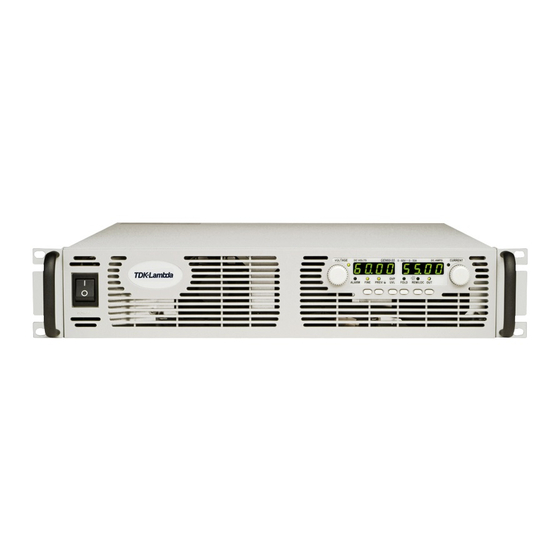
2U GENESYS 3.3kW Programmable DC Power Supplies GEN 3300W series
Brand:
TDK-Lambda
| Category:
Power Supply
| Size: 2.14 MB
Table of Contents
Table of Contents
5
Warranty
9
English Safety Instructions
10
Francais (French)
13
Deutsch (German)
16
Italiano (Italian)
19
Portuges (Portugese)
22
Español (Spanish)
25
1 General Information
28
User Manual Content
28
Introduction
28
General Description
28
Models Covered by this Manual
28
Features and Options
28
Multiple Output Power System
29
Control Via the Serial Communication Port
29
Analog Voltage Programming and Monitoring
29
Parallel Operation
29
Output Connections
30
Cooling and Mechanical Construction
30
Accessories
30
General
30
Serial Link Cable
30
Misc. Hardware
30
Ac Cables
30
2 Specifications
32
Output Rating
32
Input Characteristics
32
Constant Voltage Mode
32
Constant Current Mode
32
Analog Programming and Monitoring
32
Programming and Readback (Rs232/485, Optional Ieee Interface)
32
Protective Functions
33
Front Panel
33
Environmental Conditions
33
Mechanical
33
Safety/Emc
33
Supplemental Characteristics
34
3 Installation
36
General
36
Preparation for Use
36
Initial Inspections
37
Rack Mounting
37
To Install the Power Supply in a Rack
37
Rack Mount Slides (Optional)
37
Plastic Supporting Legs
37
Location, Mounting and Cooling
38
Ac Source Requirements
38
Ac Input Power Connection
38
Ac Input Connector
38
Ac Input Cord
39
Ac Input Wire Connection
39
Turn-On Checkout Procedure
40
General
40
Prior to Operation
40
Constant Voltage Check
40
Constant Current Check
41
Ovp Check
41
Uvl Check
41
Foldback Check
42
Address Setting
42
Baud Rate Setting (Rs-232 and Rs-485 Only)
42
Connecting the Load
42
Load Wiring
42
Current Carrying Capacity
43
Wire Termination
43
Noise and Impedance Effects
44
Inductive Loads
44
Making the Load Connections
44
Connecting Single Loads, Local Sensing (Default)
47
Connecting Single Loads, Remote Sensing
47
Connecting Multiple Loads, Radial Distribution Method
47
Multiple Load Connection with Distribution Terminals
48
Grounding Outputs
48
Local and Remote Sensing
49
Sense Wiring
49
Local Sensing
49
Remote Sensing
50
J2 Sense Connector Technical Information
50
Repackaging for Shipment
50
4 Front and Rear Panel Controls and Connectors
51
Introduction
51
Front Panel Controls and Indicators
51
Rear Panel Connections and Controls
53
Rear Panel Sw1 Setup Switch
54
Sw1 Position Function
55
Resetting the Sw1 Switch
55
Rear Panel J1 Programming and Monitoring Connector
56
Making J1 Connections
56
5 Local Operation
58
Introduction
58
Standard Operation
58
Constant Voltage Mode
58
Constant Current Mode
59
Automatic Crossover
59
Over Voltage Protection (Ovp)
59
Setting the Ovp Level
59
Activated Ovp Protection Indications
60
Resetting the Ovp Circuit
60
Under Voltage Limit (Uvl)
60
Setting the Uvl Level
60
Foldback Protection
60
Setting the Foldback Protection
60
Resetting Activated Foldback Protection
61
Output On/Off Control
61
Output Shut-Off (So) Control Via Rear Panel J1 Connector
61
Enable/Disable Control Via Rear Panel J1 Connector
62
CV/CC Signal
62
Ps_Ok Signal
62
Safe-Start and Auto-Restart Modes
63
Auto-Restart Mode
63
Safe-Start Mode
63
Over Temperature Protection (Otp)
63
Last Setting Memory
63
Series Operation
64
Series Connection for Increased Output Voltage
64
Series Connection for Positive and Negative Output Voltage
65
Parallel Operation
66
Basic Parallel Operation
66
1.Setting up the Master Unit
66
2.Setting up the Slave Units
66
3.Daisy Chain Connection: (See Fig. 5-6)
67
4.Setting over Voltage Protection
67
5.Setting Foldback Protection
67
6.Connection to the Load
67
Advanced Parallel Operation
67
1.Advanced Parallel Configuration
68
2.Connection to the Load
68
3.Setting the Units as Master or Slave
68
4.Master and Slave Units Default Operation
68
5.Current Display Accuracy
69
6.To Release Units from Slave Mode
69
Daisy-Chain Connection
70
Front Panel Locking
71
Unlocked Front Panel
71
Locked Front Panel
71
6 Remote Analog Programming
72
Introduction
72
Local/Remote Analog Control
72
Local/Remote Analog Indication
72
Remote Voltage Programming of Output Voltage and Current
73
Resistive Programming of Output Voltage and Current Limit
74
Remote Monitoring of Output Voltage and Current
75
7 Rs232 & Rs485 Remote Control
76
Introduction
76
Configuration
76
Default Setting
76
Address Setting
76
Rs232 or Rs485 Selection
76
Baud Rate Setting
76
Setting the Unit into Remote or Local Mode
76
Rs232/Rs485 Port in Local Mode
77
Front Panel in Remote Mode
77
Rear Panel Rs232/Rs485 Connector
77
Connecting Power Supplies to Rs232 or Rs485 Bus
78
Single Power Supply
78
Multi Power Supply Connection to Rs232 or Rs485 Bus
79
Communication Interface Protocol
79
Data Format
79
Addressing
79
End of Message
79
Command Repeat
80
Checksum
80
Acknowledge
80
Error Message
80
Backspace
80
Error Messages
80
Command Set Description
80
General Guide
80
Command Set Categories
81
Initialization Control Commands
81
ID Control Commands
81
Output Control Commands
81
Global Output Commands
83
Description
83
Fast Queries
84
Fast Test for Connection
84
Fast Read Registers
85
Read Power-On Time
85
Service Request Messages
86
Status and Error Commands
86
Status, Error, and Srq Registers
87
General Description
87
Conditional Registers
88
Service Request: Enable and Event Registers
89
1.Fault Enable Register
89
2.Fault Event Register
89
3.Status Enable Register
90
4.Status Event Register
90
Serial Communication Test Set-Up
91
Equipment
91
Pc Set-Up
91
Power Supply Set-Up
91
Communication Test
91
8 Isolated Analog Programming Option
92
Introduction
92
Specifications
92
0-5V/0-10V Option (Pn: Is510)
92
4-20Ma Option (Pn: Is420)
92
Isolated Programming & Monitoring Connector
93
Setup and Operating Instructions
94
Setting up the Power Supply for 0-5V/0-10V Isolated Programming and Monitoring
94
Setting up the Power Supply for 4-20Ma Isolated Programming and Monitoring
94
9 Maintenance
95
Introduction
95
Units under Warranty
95
Periodic Maintenance
95
Adjustments and Calibration
95
Parts Replacement and Repairs
95
Troubleshooting
95
Fuse Rating
96
Related Products
TDK-Lambda Genesys GEN8-90
TDK-Lambda Genesys GEN80-9.5
TDK-Lambda Genesys GEN80-19
TDK-Lambda Genesys GEN8-180
TDK-Lambda Genesys GEN8-300
TDK-Lambda Genesys GEN80-30
TDK-Lambda GEN8-600
TDK-Lambda GEN80-65
TDK-Lambda Genesys GEN30-50
TDK-LAMBDA GEN 150-22 ABCDE
TDK-LAMBDA Categories
Power Supply
Media Converter
Cables and connectors
Portable Generator
Network Hardware
More TDK-LAMBDA Manuals