beautypg.com
Manuals
Brands
Toshiba Manuals
Control Unit
nv Series
Toshiba nv Series Manuals
Manuals and User Guides for Toshiba nv Series. We have
16
Toshiba nv Series manuals available for free PDF download: Hardware Manual, Instruction Manual, User Manual, Operating Instructions (Functional Manual)
Toshiba nv Series Hardware Manual (177 pages)
Unified Controller
Brand:
Toshiba
| Category:
Controller
| Size: 2.15 MB
Table of Contents
Table of Contents
16
Chapter 1
21
Overview
21
Overview of T
21
Applicalbe Series and Contollers
22
Series Migration
22
Migration Product List
23
1.3.1 Unified Controller Type1 Products
23
T Series Migration Specific Products
25
Overview of Migration Products
26
Controller Module
26
Base Unit
27
Power Supply Module
31
Expanded Interface Module, Expanded Cable
32
TC-Net I/O Adapter Module
33
Terminal Block Signal Conversion Adapter
34
Engineering Tools
35
Series
36
T2 Series
39
CPU Module
39
Chapter 2 System Migration Procedures
39
Base Unit
40
Power Supply Module
41
Transmission Module
42
I/O Module
43
Examples of Conversion During Migration
45
Examples of Migration System Configuration
49
Conversion of User Programs
52
System
52
S2T/S2E
53
CPU Module
53
Base Unit
54
Power Supply Module
55
Transmission Module
56
I/O Module
57
Examples of Conversion
59
Examples of Migration System Configuration
64
Restrictions in Migration System
67
Conversion of User Programs
67
Chapter 3 Installation and Wiring
90
Installation Condition
92
Before Working
95
Mounting to Chassis
96
Grounding of Controller Unit and I/O Unit
97
Mounting Base Unit
101
Power Supply Wiring
102
Mounting/Dismounting Modules
105
Mounting/Dismounting Terminal Block Signal Conversion Adapter
113
Expansion of Base Unit
116
3.10 Input/Output Wiring
117
3.11 TC-Net I/O Loop Wiring
120
Chapter 4 Start and Stop
122
Safety Circuit
123
Switch Check before Starting
124
How to Start/Stop
125
LED State at Start
127
Chapter 6 Maintenance and Inspection
132
Daily Inspection
133
Periodic Inspection
134
Maintenance Parets
135
Battery Replacement
136
Control Module Replacement
137
Disposal
137
Appendix A Base Unit Bum7B
138
A.1 Specifications
139
Appendix A
139
A.2 Outline Drawing
142
A.3 Mounting Hole Dimensions
145
Power Terminal
146
Use of BUM7B by Application
148
Toshiba nv Series Instruction Manual (148 pages)
Light Controller Unit
Brand:
Toshiba
| Category:
Controller
| Size: 5.44 MB
Table of Contents
Table of Contents
17
Functions and Characteristics of the Controller
20
Chapter 1
21
Names and Functions of Parts of the Controller
21
Part Names and Functions of Serial Bus Interface Module
25
Part Names and Functions of Power Module
26
System Configuration
28
Installation Condition
34
Grounding of the Controller
37
Before Starting the Work
43
Chapter 2
44
Implementation to the Chassic
44
Grounding of the Controller and I/O Units
45
Installing the Base Unit
46
Installing/Uninstalling the Module
47
Power Wiring
56
Connection of TC-Net I/O Loop Cable
60
Connecting the Intelligent I/O
62
Ethernet Connection
63
Checking the Switch before Starting
66
Installing the Battery to the Controller Module
68
How to Start the Controller
69
The Status of LED When the Controller Is Started
70
Chapter 4 Starting and Stopping
71
How to Stop the Controller
71
If Failure Suspected
84
Chapter 7
90
Trouble Details Checks
90
Daily Inspections
98
Periodic Inspections
99
Service Parts
100
Replacing the Battery
101
Disposing of the Module
104
General Specification
106
Appendix A
108
Power Module Specification
108
Controller Module Specification
110
Serial Bus Interface Module Specification
111
Base Unit Specification
111
Life-Time Components
112
List of TC-Net I/O Modules and Other Related Modules
113
List of Intelligent I/O Modules and Other Related Modules
114
List of Intelligent I/O Modules and Other Related Modules
115
List of Current Consumptions and Weights by Module
117
List of Current Consumptions and Weight by Modules
117
Cables
120
Cable
120
Blank Module
120
Base Unit
122
Appendix B
123
Power Module
123
Controller Module
124
Serial Bus Interface Module
125
Appendix C
127
DC Input Modules
127
AC Input Modules
133
DC Output Modules
136
AC Output Modules
139
Analog Input Modules
140
Analog Output Modules
141
Migration Method
144
Toshiba nv Series Instruction Manual (122 pages)
Brand:
Toshiba
| Category:
Controller
| Size: 1.9 MB
Table of Contents
Table of Contents
11
Functions and Characteristics of the FL911 Module
16
Names and Functions of the Parts
18
Names of the Parts
18
Functions of the Parts
19
Types of I/O Base Units
24
Installing the Module
25
Replacing the Module
28
Switch Setting
30
TC-Net I/O Bus Address Switch (I
30
Node Address Setting Switch (STN-H, STN
30
TC-Net I/O Bus Address Switch (I/O)
30
Node Address Setting Switch (STN-H, STN-L)
30
Operation Mode Setting Switch (MODE)
31
Maintenance Switch (MAINT)
31
Network Parameter Setting
32
Network ID and Subnet Mask
32
Node Address
32
Module Parameter Setting
32
Setting with the Engineering Tool
33
Module Parameter Setting
34
Adding of Network
38
Setting Network Variables
40
Setting FL911 RAS Variables
43
Inspection
58
Daily Inspection
58
Maintenance and
58
Periodical Inspection
59
Life Limited Parts
59
Message Transmission
63
Supported Message Transmission Service Types
63
XMIT_N Function Block
64
Message Transmission Client Request
65
Request Command/Transmission Data
65
Command/Transmission Data
65
Communication Data of Message Transmission
70
Completion Status
75
Mread_N, Mwrite_N
77
SW Healthy Information
78
HW Version Information
78
SW Version Information
78
Message Flag
78
Online Map
79
Cyclic Data Validity Map
80
Station Status
81
Down Information
82
Initialization Complete
82
Node Number
83
IP Address
83
MAC Address
83
Device Profile
83
Log Information Area
84
Management Information Area
86
Usage Constraints
89
Assignment of FL911 Management Blocks
90
General Specifications
94
FL911 Transmission Specifications
95
Function Specifications
96
Serial Communication Port (RS-232C) Transmission Specifications
96
Introduction
106
Attention
106
FL654 Module Parameters
107
FL654 Connect Route
108
Parameters
109
Data
109
System View
110
Station Status Display
111
Main Module Details
111
Version Display
112
Time Setting
112
Run Mode Setting
113
LAN Management Information Screen
114
Scan Healthy Map
115
Memory Clear
116
System Log
117
Toshiba nv Series Instruction Manual (124 pages)
DeviceNet Module
Brand:
Toshiba
| Category:
Controller
| Size: 5.07 MB
Table of Contents
Table of Contents
15
DN912 Introduction
17
Functions and Features of the DN912
18
System Configurations
19
Devicenet Network Configurations
21
Devicenet Network Configuration
21
Network Configuration
21
Trunk Line / Drop Line and Maximum Cable Length
21
Terminating Resistor
25
Standards
26
Basic Functions
27
Poll Command / Response Method
27
Bit-Strobe Command / Response
28
Data Update Cycle of Controller and DN912
30
Names of Parts
32
Functions of Parts
33
Chapter 3 Install and Wiring
37
Types of I/O Base Unit
40
Module Installation
41
Vertical Mounting of the Module
41
Horizontal Mounting of Module
44
Connection of TC-Net I/O Loop Transmission Connector
45
Connecting Devicenet Cable to Connector
47
Connecting the Devicenet Transmission Cable
47
Network Side Connector
48
Connecting Devicenet Cable to Connector
49
Network Power and Ground
50
Network Power Supply Method
50
Network Configuration Method
51
Network Power Supply
57
Network Grounding
58
Replacing the Module
59
Removing the Module / Base Unit
60
Chapter 4 Settings
61
Devicenet Communication Speed and Node Address Setting Switch
62
Switches Setting
62
TC-Net I/O Loop Address Setting Switch
62
DN912 Scan Block
63
DN912 Module Parameters
64
Devicenet Network Setting
66
Master Node Settings
68
Creating a New Project and Setting the Device Configuration
70
Setting with Engineering Tool
84
DN912 Registration
85
Register Network Variables
88
Setting RAS Variables for DN912
91
Check before Starting
94
How to Start
94
How to Stop
96
Ras
98
Troubleshooting
103
Chapter 7 Maintenance and Inspection
105
Maintenance and Inspection
105
Daily Inspection
106
Inspection
106
Periodic Inspection
107
Maintenance Parts
108
Specifications
108
Combination Version
110
Maximum Number of DN912 Units
110
Appendix A Specifications
111
General Specifications
112
DN912 and BU90A Specifications
113
DN912 Communication Specifications
114
DC24V System Power Supply Specifications
115
Outside Dimension
117
Related Products
119
Network Components
120
Devicenet Setting Tool
122
Toshiba nv Series Instruction Manual (138 pages)
Controller Unit
Brand:
Toshiba
| Category:
Controller
| Size: 2.46 MB
Table of Contents
Table of Contents
16
Functions and Characteristics of the Controller
20
Chapter 1
22
Names and Functions of Parts of the Controller
22
Names and Functions of the Parts of the Power Supply
24
System Configuration
28
Installation Condition
34
Grounding of the Controller
38
Base Unit / Fan Unit
43
Chapter 2
46
Installing / Uninstalling the Module
46
Implementation to the Body
49
Connection of the External Line I/O
52
Chapter 3
54
Connection of TC-Net I/O Loop Cable
54
Connection with the Nv-Tool Cable
56
Checking the Switch before Starting
58
Chapter 4
59
Installing the Battery to the Controller Module
59
How to Start the Controller
60
The Status of LED When the Controller Is Started
61
How to Stop the Controller
62
If a Trouble Is Suspected
74
Chapter 7
80
Trouble Details Checks
80
Version Checks
88
Daily Inspections
90
Chapter 8
91
Periodic Inspections
91
Service Parts
92
Replacing the Battery
93
Replacing the Shutdown Capacitor
95
Replacing and Cleaning the Filter
97
Disposing of the Module
100
General Specification
102
Appendix A
104
Power Module Specification
104
Controller Module Specification
106
Life-Time Components
107
List of TC-Net I/O Modules and Other Related Modules
108
List of Current Consumptions and Weights by Module
109
Base and Fan Units
112
Appendix B
116
Power Module PS891
116
Controller Modules PU811 and PU812
117
DC Input Modules
120
Appendix C
125
AC Input Modules
125
DC Output Modules
128
AC Output Modules
131
Contact Output Modules
132
Analog Input Modules
134
Analog Output Modules
134
Toshiba nv Series Instruction Manual (104 pages)
type2 SOE Function Unified Controller
Brand:
Toshiba
| Category:
Control Unit
| Size: 3.29 MB
Table of Contents
Safety Precautions
3
Table of Contents
17
Functions and Characteristics of the SA9A1 Module
22
Names and Functions of the Parts
25
Names of the Parts
25
Functions of the Parts
26
Chapter 1 Introducing the SA9A1 Module
29
Chapter 2 Installation and Wiring
29
Types of I/O Base Units
32
Installing the Module
33
Vertical Installing of the Module
33
Horizontal Installing of the Module
37
Connecting the TC-Net I/O Loop Transmission Cable
38
Replacing the Module
39
Removing the Base Unit
40
Switch Setting of the SA9A1
42
Loop Address Setting Switch (STN-H, STN-L)
42
Operation Mode Setting Switch (MODE)
43
Maintenance Switch (MAINT)
43
Chapter 3 Setting
44
Setting with the Engineering Tool
44
Module Parameter Setting
45
SOE Guidance Tag Registration
53
Time Service Module TS811
56
TS811 Function
56
About Leap Second Correction
57
OIS-DS Engineering Tool
59
Event Condition
59
Program Menu
60
Guidance
61
Checking the Switch before Startup
64
Startup of the System
64
Chapter 4 Startup/Shutdown and Operation
64
Shutdown of the System
65
Start SOE Information
66
Start from Guidance
66
Show SOE Information
66
Start from TOSDIC-CIE DS OIS-DS Program
67
Show SOE Information
68
Switch Node
70
Update Event Run Mode
71
SOE Restart
72
Save CSV File
73
Close SOE Information
74
Chapter 5
75
Troubleshooting
75
Chapter 6 Maintenance and
79
Inspection
80
Daily Inspection
80
Checking the Switch before Startup
80
Periodical Inspection
82
Maintenance Parts
83
Life Limited Parts
83
Usage Constraints
86
Combination with the Other Modules and Engineering Tool
86
Implementation Constraints
86
Chapter 7 Application Interface
87
About TS811 Diagnostic
87
TS811 Diagnostic Function
87
Sample Program 1
87
Sample Program 2
88
Specifications
89
Appendix A
90
Common Specifications
90
SA9A1 Specifications
91
BU901 Specifications
92
24VDC System Power Supply Specifications
92
Toshiba nv Series Instruction Manual (104 pages)
Unified Controller
Brand:
Toshiba
| Category:
Controller
| Size: 1.04 MB
Table of Contents
Table of Contents
11
Functions and Characteristics of the EN811 Module
16
Names and Functions of the Parts
18
Introducing the
18
Names of the Parts
18
Functions of the Parts
19
Installation (Installation to the Basic Unit)
22
Connecting the Ethernet Cable
24
Connecting the Serial Communication Port (RS-232C)
25
Cable
25
Replacing the Module
26
Switch Setting
30
Station Address Setting Switch
30
(Stn-H, Stn
30
Operation Mode Setting Switch (MODE)
31
Network Parameter Setting
32
Network ID and Subnet Mask
32
Station Address
33
Overview of Multicast Address
33
Setting with the Engineering Tool
35
Network Parameter Setting
36
Multicast Address Setting
45
Multicast Routing Network Setting
47
Ethernet Link Speed/Duplex Setting
48
(Router IP Address) Setting
49
Option Function
51
Network Information
52
LAN Control Information
52
MIB Information
53
Chapter 6 Maintenance and Inspection
59
Daily Inspection
60
Inspection
60
Life Limited Parts
61
Periodical Inspection
61
Chapter 7 Application Interface
63
Configuration of Information by Single Ethernet Socket
65
Information by Socket
65
Referring to Information by Socket
66
Timing of Generation of Information by Socket53
67
Configuration of Transmission Path Diagnosis Information
69
Transmission Path Diagnosis Information
69
Referring to Transmission Path Diagnosis Information
70
Configuration of a Transmission Path Diagnosis Frame
71
EN811 Module State Information
72
Frame Size Constraints
73
Port Number Constraints
73
Usage Constraints
73
Program (Udp Transmission)
89
Open_Status1
91
Complete
92
Open
92
Open_Complete
93
Open_Error
93
Open_Req
93
Open_Status1
93
Send_Status
93
Tx_Complete
93
Tx_Error
93
Usend_N
93
Usend_N_1
93
Usend_N_2
93
Open_Error
95
Toshiba nv Series Instruction Manual (95 pages)
Ethernet (FN812) Module
Brand:
Toshiba
| Category:
Control Unit
| Size: 1.52 MB
Table of Contents
Table of Contents
11
Functions and Characteristics of the FN812 Module
15
Names and Functions of the Parts
17
Names of the Parts
17
Functions of the Parts
18
Installation (Installation to the Basic Unit)
21
Connecting the Ethernet Cable
23
Connecting the Serial Communication Port (RS-232C)
24
Cable
24
Replacing the Module
25
Switch Setting
29
Station Address Setting Switch
29
(Stn-H, Stn
29
Station Address Setting Switch (STN-H, STN
29
Operation Mode Setting Switch (MODE)
30
Network Parameter Setting
31
Station Address
31
Overview of Multicast Address
31
Setting with the Engineering Tool
33
Network Parameter Setting
34
Multicast Address Setting
43
Network Information
45
LAN Control Information
45
MIB Information
46
Inspection
54
Daily Inspection
54
Periodical Inspection
54
Life Limited Parts
55
Information by Socket
58
Configuration of Information by Single Ethernet Socket
58
Socket 0
58
Configuration of Information by Redundant Ethernet Socket
59
Socket
59
Referring to Information by Socket
60
Timing of Generation of Information by Socket
61
FN812 Module State Information
63
Usage Constraints
64
Port Number Constraints
64
Frame Size Constraints
64
Single Ethernet Socket and Redundant Ethernet Socket Constraint
64
Multicast Address Constraint
64
Single Ethernet Socket and Redundant
64
Ethernet Socket Constraint
64
General Specifications
67
Ethernet Transmission Specifications
68
Function Specifications
68
Serial Communication Port (RS-232C) Transmission
69
Specifications
69
Toshiba nv Series Instruction Manual (104 pages)
Ethernet module
Brand:
Toshiba
| Category:
Control Unit
| Size: 5.77 MB
Table of Contents
Table of Contents
11
Functions and Characteristics of the EN655 Module
16
Names and Functions of the Parts
19
Names of the Parts
19
Functions of the Parts
19
Types of I/O Base Units
24
Installing the Module/Removing the Module
25
Replacing the Module
28
Switch Settings
30
Station Address Setting Switch (STN-H, STN-L)
30
Station Address Setting Switch (STN-H、STN-L)
30
Operation Mode Setting Switch (MODE)
31
Network Parameter Settings
32
Network ID and Subnet Mask
32
Station Address
33
Multicast Address
33
Setting Using the Engineering Tool
34
Module Parameter Setting
35
Network Information
39
MIB Information
39
EN655 Shared Memory Map
46
EN655 Module Information
46
Communication Using the Socket Interface
68
Communication Using the Computer Link/ PC Link
69
Settings and Related Instruction Words
71
Socket Interface Information
72
Station Status
73
Usage Restrictions
74
Port Number Restrictions
74
Combination with the Engineering Tool and Other Modules
74
Transmission Constraints of the EN655
75
Implementation Constraints
75
Notes When Changing from EN311
76
Examples for Using the Instruction Words
78
UDP Communication
78
TCP Communication
83
Toshiba nv Series Instruction Manual (80 pages)
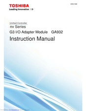
Unified Controller, I/O Adapter Module
Brand:
Toshiba
| Category:
Controller
| Size: 2.24 MB
Table of Contents
Table of Contents
11
Functions and Characteristics of GA932 Module
14
System Configuration
16
Data Input/Output with G3 I/O Module
18
Online Map/Online Status for G3 I/O Module
19
Chapter 1 Introducing GA932 Module
20
Names and Functions of the Parts
20
Names of the Parts
20
Functions of the Parts
21
Types of I/O Base Units
25
Chapter 2
26
Installing / Removing the Module
26
TC-Net I/O Loop Wiring
29
Replacing the Module
31
Handling the RUN Signal (RUN Contact) of G3 I/O
32
Switch Setting
34
Operation Mode Setting Switch (MODE)
34
Maintenance Switch (MAINT)
35
Node No. Setting Switches
35
Chapter 3 Setting
36
Setting with the Engineering Tool
36
I/O Node Registration
37
Association G3 I/O Adapter and I/O Node Number and Setting I/O Loop Scan Speed
39
Number and Setting I/O Loop Scan Speed
39
G3 I/O and I/O Module Registration
41
I/O Variables Registration
44
Checking the Switch before Startup
48
Chapter 4
48
Startup
48
Shutdown
49
Inspection
61
Daily Inspection
61
Periodical Inspection
62
Chapter 6 Maintenance and Inspection
63
Maintenance Parts
63
Life Limited Parts
63
Specifications a
65
General Specifications
66
Appendix A
67
Function Specifications
67
G3 I/O Module Support List
68
TC-Net I/O Loop Transmission Specifications
72
Operating Instruction for Specific Modules
73
Operating Instructions for Specific Modules
73
Toshiba nv Series Instruction Manual (100 pages)
Brand:
Toshiba
| Category:
Controller
| Size: 2.44 MB
Table of Contents
Table of Contents
15
Outline
18
Chapter 1
19
System Configuration
19
Constraints and Operational Conditions
21
Secure Package Configuration
24
Recommended Configuration
25
Vulnerability Contact Point
28
Installation
31
Chapter 2
35
Uninstallation
35
Unused Service
39
Chapter 3
43
Windows Defender Firewall
43
Whitelist Type Security Software
50
Switch of FN812S
51
Outline
56
Chapter 4
58
Authentication
58
Authentication Screen
68
Authentication History
81
Toshiba nv Series Instruction Manual (84 pages)
TC-net I/O Serial Communication Module IS911
Brand:
Toshiba
| Category:
Controller
| Size: 2.87 MB
Table of Contents
Table of Contents
11
Functions and Characteristics of the IS911 Module
14
Names and Functions of the Parts
16
Names of the Parts
16
Functions of the Parts
17
Serial Communication and Network Configuration
19
SYSMAC Host Link Serial Communication
19
MELESEC Computer Link Serial Communication
21
Types of I/O Base Units
26
Installing IS911 Module
27
Replacing IS911 Module
31
Remove
31
Installation
31
Transmission Cable Connection
32
Connection with SYSMAC (CS1W-SCB41-V1)
32
Connection with SYSMAC (C500-LK201)
33
Connection with MELSEC a Series (AJ71UC24)
34
Connection with MELSEC Q Series (QJ71C24N)
35
Switch Setting
38
TC-Net I/O Bus Address Switch (I/O)
38
Operation Mode Setting Switch (MODE)
38
Maintenance Switch (MAINT)
39
IS911 Module Registration and Parameter Setting
40
System Registration
43
PLC Registration
45
Module Parameter Setting
47
Talker Block Setting
51
RAS Data Variables Registration
56
Operation
58
Checking before Operation
58
Startup Operation
58
Stop Operation
58
Troubleshooting
60
Fault Diagnosis Method Using LED
60
Loading System Log and RAS Data
61
Error Code
62
Others
63
OIS Alarm Display
64
Toshiba nv Series Instruction Manual (72 pages)
Unified Controller Ethernet (EN911) Module
Brand:
Toshiba
| Category:
Controller
| Size: 1.26 MB
Table of Contents
Table of Contents
11
Functions and Characteristics of the EN911 Module
14
Chapter 1 Names and Functions of the Parts
16
Names of the Parts
16
Functions of the Parts
17
Types of I/O Base Units
22
Chapter 2
23
Installing the Module
23
Replacing the Module
26
Switch Setting
28
TC-Net I/O Bus Address Switch (I/O)
28
Node Address Setting Switch (STN-H, STN-L)
28
Operation Mode Setting Switch (MODE)
29
Maintenance Switch (MAINT)
29
Chapter 3 Setting
30
Network Parameter Setting
30
Network ID and Subnet Mask
30
Station Address
30
Multicast Address
31
Setting with the Engineering Tool
32
Module Parameter Setting
33
Setting EN911 I/O Variables
37
Network Information
40
MIB Information
40
Chapter 6 Maintenance and Inspection
47
Inspection
48
Daily Inspection
48
Periodical Inspection
49
Life Limited Parts
50
Chapter 7 Application Interface
51
Information by Socket
52
Configuration of Information by Ethernet Socket
52
Referring to Information by Socket
53
Timing of Generation of Information by Socket
54
Usage Constraints
56
Port Number Constraints
56
Transmission Path Diagnosis Information
56
Combination with the Other Modules and Engineering Tool
56
Use of EN911 Reset Command
56
Transmission Limitations of EN911
57
Limitations on Installation
58
Appendix A Specifications
59
A.1 General Specifications
60
Appendix A
60
A.2 EN911 Transmission Specifications
61
A.3 Function Specifications
62
Serial Communication Port (RS-232C)
62
Transmission Specifications
62
Toshiba nv Series User Manual (70 pages)
type1 light PROFIBUS-DP Module
Brand:
Toshiba
| Category:
Control Unit
| Size: 4.12 MB
Table of Contents
Table of Contents
15
Features of PF611A / PF612A Module
18
System Configuration Example
19
Chapter 2 Name and Function of Module Components
21
External View
22
Name of PF611A Module Components and Parts
24
Name of PF612A Module Components and Parts
26
Configurator
30
Chapter 3 Operation, Function and Setup
31
Setting
32
Cyclic Transmission
33
Transmission Parameter Setup
34
Registration and Setup
35
Module Control Information
38
Reset PF Module
38
PF611A Information that Can be Referenced as I/O Connection
40
PF611A Information Referenced with MREAD Instruction
44
PF612A Information that Can be Referenced as I/O Connection
46
Error Inspection
48
Chapter 7 Maintenance and Inspection
51
Daily Inspection
52
Inspection
52
Periodical Inspection
53
Maintenance and Inspection
54
Maintenance Parts
54
Appendix A Specifications
55
General Specification
56
General Specifications
56
Specifications A.3 Module Specification
56
Transmission Specification
57
Transmission Specifications
57
Module Specifications
58
Limitations
59
External Dimensions
60
Controller Interface DPRAM Memory Map
61
Registering the Module
64
Registering the LAN
66
Registration and
66
Registering and Assigning Network Variables
67
Toshiba nv Series Operating Instructions (Functional Manual) (49 pages)
TC-net I/O system 8ch-Pulse Input Module PI918
Brand:
Toshiba
| Category:
Controller
| Size: 1.33 MB
Table of Contents
Table of Contents
18
Configuration of the Module Front Panel
21
Chapter 1 PI918 Function Setting Parameters
22
Module Parameter (Common Function Setting)
22
Point Parameter (Function Setting by Channel)
22
PI918 Message Reception Format
25
Module Parameter Setting (Common Function Setting)
26
Point Parameter Setting (Function Setting by Channel)
27
Chapter 2 Interface Information of
28
PI918 Scan Reception Format
28
PI918 Scan Transmission Format
29
Operation of the Universal Counter
32
Application as a Programmable Interrupt Occurrence
33
Application as an Auto Reset Universal Counter
34
Application as a Gate on Timer with Alarm
35
Application as a Universal Counter with Alarm
36
Chapter 3 Counter Function of the PI918
37
Operation of the Speed Counter
37
Application as a Self Diagnosis Counter
38
Application as a Speed Counter with Alarm
39
Operation of the Slave Counter
40
Application as a Slave Cycle Counter
41
Application as a Slave Counter with Alarm
42
Toshiba nv Series Instruction Manual (48 pages)
Serial Bus Interface Module
Brand:
Toshiba
| Category:
Control Unit
| Size: 2.3 MB
Table of Contents
Chapter 1 Introducing the Sb812 Module
13
Functions and Characteristics of the SB812 Module
14
Names and Functions of the Parts
17
Names of the Parts
17
Functions of the Parts
18
Chapter 2 Installation and Wiring
19
Installation (Installation in the Basic Unit)
20
Connection of Serial Bus Cable
22
Laying of Serial Bus Cable
25
Replacement of the Module
28
Related Products
Toshiba NV Series
Toshiba NVR8-X
Toshiba NVR16-X
Toshiba Surveillix NVS16-X
Toshiba Surveillix NVS32-X
Toshiba Surveillix NVS8-X
Toshiba Surveillix NVSProX-2U-X
Toshiba Surveillix NVSProX-4U-X
Toshiba nv-pack Series
Toshiba nv-pack
Toshiba Categories
Laptop
Air Conditioner
TV
LCD TV
All in One Printer
More Toshiba Manuals