beautypg.com
Manuals
Brands
Toshiba Manuals
UPS
T901H1D6MWWW-C
Toshiba T901H1D6MWWW-C Manuals
Manuals and User Guides for Toshiba T901H1D6MWWW-C. We have
1
Toshiba T901H1D6MWWW-C manual available for free PDF download: Installation And Operation Manual
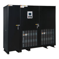
Toshiba T901H1D6MWWW-C Installation And Operation Manual (100 pages)
480/480 V 300/500/650/750 kVA
Brand:
Toshiba
| Category:
UPS
| Size: 6.19 MB
Table of Contents
Table of Contents
5
List of Tables
6
1 How to Use this Manual
9
1.1 Notice Icons
9
1.2 Qualified Personnel
10
2 Introduction
11
2.1 Safety Precautions
12
Table 2-1 UPS Installation Environment
13
Table 2-2 Rating of Bypass Input Circuit Breaker
14
3 General
15
Definitions
16
Operation Overview
17
Normal Operation: Load Power Supplied by each System UPS Inverter
17
Figure 3-1 Single Line Diagram - Normal Operation: Load Powered by UPS Inverter
17
Bypass Operation: Load Power Supplied through UPS Internal Static Bypass Line
18
Figure 3-2 Single Line Diagram - Bypass Operation: Load Fed through Static Bypass Line
18
Battery Operation: Load Power Supplied by UPS Battery
19
Figure 3-3 Single Line Diagram - Battery Operation
19
Battery Charging Operation
20
Figure 3-4 Typical Battery Charging Curve
20
UPS Parts Location
21
Figure 3-5 UPS Parts Location (300Kva)
21
Figure 3-6 UPS Parts Location (500Kva)
22
Figure 3-7 UPS Parts Location (650Kva & 750Kva)
23
PCB Layouts
24
Table 3-1 Circuit Breaker/Contactor Function
24
Table 3-2 DPAU-81 Switch/Button Function
24
Figure 3-8 Display PCB DPAU-81
24
Figure 3-9 External I/F PCB IOAU-09
25
Figure 3-10 Parallel I/F PCB IFAU-09
25
Figure 3-11 MAIN PCB UPGR-M
25
Figure 3-12 MAIN PCB UPJR-C
26
Specifications
28
Table 3-3 Power Specifications
28
Table 3-4 UPS Module Information
28
Table 3-5 Detail of Specifications
29
Table 3-6 Typical UPS Efficiencies at Various Loads
31
Table 3-7 MTBF and MTTR
31
Table 3-8 Rating of Contactors, Breakers and Fuses
32
4 Operator Controls and Indicators
33
Led Display
33
Figure 4-1 Operation/Display Panel (Front Panel)
33
EPO BUTTON (Emergency Power off Button) (7)
34
Liquid Crystal Display (8)
34
Test Mode Options
34
Menu
34
Figure 4-2 Main Screen
35
Figure 4-3 Startup/Shutdown Guidance
35
Figure 4-4 Startup Guidance
36
Figure 4-5 Shutdown Guidance
36
Figure 4-6 Input Values
36
Figure 4-7 Battery Operation Values
36
Figure 4-8 Output Values
36
Figure 4-9 Remote/Local Operation Select
37
Figure 4-10 Date & Time Adjustment
37
Figure 4-11 Log Menu
37
Input Power Failure
38
Figure 4-12 Event Log
38
Figure 4-13 Battery Log
38
Figure 4-14 Main Screen (Battery Operation)
38
Figure 4-15 Measurement Screen (Battery Operation)
38
Fault Indication
39
External Aux Contact Input and Output Terminal Blocks
39
Aux Contacts - Input
39
Figure 4-16 Main Screen (Fault Indication)
39
Figure 4-17 Message Screen
39
Figure 4-18 Control Wiring for Aux Input Contacts
40
Figure 4-19 External Signal Input Terminal Block (with Default Settings)
41
Aux Contacts - Output
42
Table 4-1 External Input Functions
42
Figure 4-20 Control Wiring for Aux Output Contacts
43
Figure 4-21 External Signal Output Terminal Block (with Default Settings)
43
Table 4-2 External Output Functions
44
Remoteye Introduction
45
Figure 4-22 Remoteye
45
Installation (Overview 300Kva)
45
Figure 4-23 Remoteye® Installation (Overview 500-750Kva)
46
Figure 4-24 Connection between Display Control PCB (SW1) and Remoteye
47
Module
47
Table 4-3 Parts List for UPS Monitoring
48
Figure 4-25 PSAU-60 PCB (PS1)
48
Figure 4-26 DPAU-81 (SW1)
48
Figure 4-27 3BBA0083P001 (Cable1)
48
Connector Definition
49
Figure 4-28 Connector (CN1) of PSAU-60 (PS1)
49
Figure 4-29 Terminal Block (TN) and VH Connector (CN2) of PSAU-60 (PS1)
49
Figure 4-30 Connector (CN44) of PSAU-60 (PS1)
49
Figure 4-31 Connector (CN27) of DPAU-60 (SW1)
49
5 Installation and Operation
50
Transportation and Installation
50
Installation Procedure
50
Table 5-1 Transport by Overhead Crane
50
Table 5-2 List of UPS Weights
50
Procedure for Cable Connections
51
Table 5-3 Maximum Recommended Fault Current
51
Table 5-4 Recommended Cable Sizes
54
Table 5-5 Crimp Type Compression Lug
55
Figure 5-1 UPS Terminal Designation
55
Figure 5-2 Diagram of Input/Output Bus Bars and Terminal Blocks (300Kva)
56
Figure 5-3 Diagram of Input/Output Bus Bars and Terminal Blocks (500Kva)
57
Figure 5-4 Diagram of Input/Output Bus Bars and Terminal Blocks (650Kva & 750Kva)
58
Figure 5-5 Detail of the Main Cabinet Bus Bars (300Kva)
59
Figure 5-6 Detail of the Main Cabinet Bus Bars (500Kva)
60
Figure 5-7 Detail of the Main Cabinet Bus Bars (650Kva & 750Kva)
61
Figure 5-8 Bus Bar Connection between Main Cabinet and Landing Cabinet (300Kva)
62
Figure 5-9 Bus Bar Connection between Main Cabinet and Landing Cabinet (500Kva)
63
Figure 5-10 Bus Bar Connection between Main Cabinet and Landing Cabinet (650Kva & 750Kva)
64
Figure 5-11 Diagram of Power Wire & Control Wire Inter-Connect between UPS and Battery
65
Figure 5-12 Diagram of Power Wire Connections (Parallel System Configuration)
66
Figure 5-13 Diagram of Communication, Power & Control Wire Connections for 2 Units in MMS Configuration (300- 750Kva)
67
Figure 5-14 Detail of IFAU-09 Control Wire Connections for 2 Units in MMS Configuration (300-750Kva)
68
Figure 5-15 Diagram of Power Wire & Control Wire Connections for 3-4 Units in MMS Config. (300-750Kva)
69
Figure 5-16 Detail of IFAU-09 Control Wire Connections for 3 or 4 Units in MMS Configuration
70
Figure 5-17 Diagram of Power Wire & Control Wire Connections for 5 to 8 Units in MMS Configuration (300-750Kva)
71
Figure 5-18 Detail of IFAU-09 Control Wire Connections for 5 to 8 Units in MMS Configuration (300-750Kva)
72
Operating Procedures
73
Figure 5-19 Circuit Protectors Location
73
Figure 5-20 Automatic Startup of Inverter and Converter
74
Figure 5-21 Close Battery Breaker
74
Figure 5-22 Press and Hold START Button
74
Figure 5-23 Transfer from Online to Bypass
75
Figure 5-24 Transfer from Bypass to Online
75
Figure 5-25 Initiate Shutdown
76
Figure 5-26 UPS Transfers to Bypass
76
Figure 5-27 Open Battery Breaker
77
Figure 5-28 LCD Screen (MMS Operation)
78
6 Response to Ups Failure
79
7 Parts Replacement
80
Table 7-1 Standard Replacement Parts List
80
8 Fault Codes
81
Table 7-2 Air Filters
81
Table 8-1 List of Fault Codes
81
9 Daily Inspection
86
Table 9-1 How to Perform Daily Inspection
86
APPENDIX A - Installation Planning Guides (IPG) & Outline Drawings
87
APPENDIX B - Index
97
Related Products
Toshiba T901H1D0MWWW-C
Toshiba T901H1D3MWWW-C
Toshiba T901H1D5MWWW-C
Toshiba T901H2D0MWWW-C
Toshiba T90S3S16KS6XSN
Toshiba T90S3S22KS6XSN
Toshiba T90N3P50KPAXSN
Toshiba T90S3S50KS6XSN
Toshiba T90S3S65KS6XSN
Toshiba T90S3S75KS6XSN
Toshiba Categories
Laptop
Air Conditioner
TV
LCD TV
All in One Printer
More Toshiba Manuals