beautypg.com
Manuals
Brands
Wacker Neuson Manuals
Portable Generator
GP 5600A
Wacker Neuson GP 5600A Manuals
Manuals and User Guides for Wacker Neuson GP 5600A. We have
4
Wacker Neuson GP 5600A manuals available for free PDF download: Operator's Manual, Repair Manual
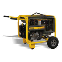
Wacker Neuson GP 5600A Operator's Manual (240 pages)
Brand:
Wacker Neuson
| Category:
Portable Generator
| Size: 32.64 MB
Table of Contents
Français
84
Table of Contents
84
Démarrer-GP2500A
122
Arrêt-GP2500A
122
Démarrer-GP3800A, GP5600A, GP6600A
123
Arrêt-GP3800A, GP5600A, GP6600A
124
Procédure D'arrêt D'urgence
124
Entretien
125
Maintenance du Système de Contrôle D'émissions
125
Calendrier D'entretien Périodique
125
Remplacement de L'huile Moteur
126
Entretien du Filtre à Air
127
Nettoyage et Inspection de la Bougie D'allumage
128
Nettoyage du Séparateur
129
Réglages du Carburateur
129
Vitesse du Moteur
130
Stockage
130
Guide de Dépannage
131
Caractéristiques Techniques
132
Générateur-GP2500A et GP3800A
132
Générateur-GP5600A et GP6600A
133
Moteur-GP2500A et GP3800A
134
Moteur-GP5600A et GP6600A
135
Instructions de Montage - Jeu de Roues
137
Informations Sur le Système Antipollution et Sa Garantie - Moteur à Essence
142
Information de Base Sur le Système de Contrôle D'émissions
142
Garantie Limitée pour les Défauts du Système de Contrôle des
143
Émissions D'échappement
143
Garantie Limitée Contre les Défectuosités pour les Systèmes de Contrôle D'émissions Évaporatives de Wacker Neuson
143
Garantie Limitée pour les Défauts du Système de Contrôle des
146
Émissions D'échappement
146
10 Schémas
148
Schémas-GP2500A
148
Schéma Électrique-Parties Constituantes
149
Schémas-GP3800A
150
Composants du Schéma Électrique
151
Schémas-GP5600A
152
Composants du Schéma Électrique
153
Schémas-GP6600A
154
Composants du Schéma Électrique
155
Prefacio
161
Español
165
Información de Seguridad
169
Palabras de Señalización que Se Utilizan en Este Manual
169
Descripción y Propósito de la Máquina
170
Seguridad en la Operación
171
Seguridad en el Mantenimiento
175
Seguridad para el Operador del Motor
175
Calcomanías
179
Ubicación de las Calcomanías
179
Significado de las Calcomanías
181
Levaje y el Transporte
186
Operación
187
Preparación para el Uso Inicial
187
Supresor de Chispas
187
Recarga de Combustible en la Máquina
188
Campos de Requerimientos de Potencia
189
Combustible Recomendado
189
Instalación
190
Posicione el Generador para Ponerlo en Marcha
191
Pérdida de Potencia del Generador
193
Manejo de Cargas Pesadas
194
Puesta a Tierra del Generador
194
Uso de Cables de Extensión
195
Tablero de Mando-GP2500A
196
Tablero de Mando-GP3800A
196
Tablero de Mando-GP5600A
197
Tablero de Mando-GP6600A
198
Interruptor del Circuito de Falla a Tierra (GFCI)
199
Auto Ralentí del Motor
200
Interruptor de Circuito
200
Receptáculos de Bloqueo de Torsión
200
Velocidad del Motor
200
Selección de Voltaje-GP3800A, GP5600A, GP6600A
201
Antes de Arrancar
202
Detención-GP2500A
203
El Arranque-GP2500A
203
El Arranque-GP3800A, GP5600A, GP6600A
204
Detención-GP3800A, GP5600A, GP6600A
205
Procedimiento de Parada de Emergencia
205
Calendario de Mantenimiento Periódico
206
Mantenimiento
206
Mantenimiento del Sistema de Control de Emisiones
206
Cambio del Aceite de Motor
207
Mantenimiento del Filtro de Aire
208
Limpieza y Verificación de la Bujía
209
Ajustes del Carburador
210
Limpieza de la Copa de Sedimentos
210
Almacenamiento
211
Velocidad del Motor
211
Localización de Problemas
212
Datos Técnicos
213
Generador-GP2500A y GP3800A
213
Generador-GP5600A y GP6600A
214
Motor-GP2500A y GP3800A
215
Motor-GP5600A y GP6600A
216
Instrucciones de Montaje: Juego de Ruedas
217
Información Básica sobre el Sistema de Control de Emisiones
222
Información y Garantía de Los Sistemas de Control de Emisiones
222
De Escape
223
Garantía Limitada por Defectos de Los Sistemas de Control de Emisiones Evaporativas Wacker Neuson
223
Garantía Limitada por Defectos del Sistema de Control de Emisiones
223
Declaración de Garantía sobre el Control de las Emisiones Evaporativas de California
226
De Escape
229
Garantía Limitada por Defectos del Sistema de Control de Emisiones
229
10 Esquemas
230
Esquemas-GP2500A
230
Esquema Eléctrico-Piezas
231
Esquemas-GP3800A
232
Componentes Eléctricos Esquemáticos
233
Esquemas-GP5600A
234
Componentes Eléctricos Esquemáticos
235
Esquemas-GP6600A
236
Componentes Eléctricos Esquemáticos
237
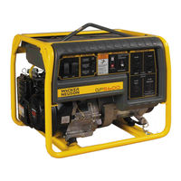
Wacker Neuson GP 5600A Repair Manual (130 pages)
Brand:
Wacker Neuson
| Category:
Portable Generator
| Size: 21.39 MB
Table of Contents
Table of Contents
5
1 Safety Information
8
Operating Safety
9
Operator Safety While Using Internal Combustion Engines
11
Service Safety
12
Label Locations
13
Safety and Operating Labels
14
2 Technical Data
18
Generator-GP 2500A
18
Engine-GP 2500A
19
Generator-GP 3800A, GP 3800A CAN
20
Engine-GP 3800A, GP 3800A CAN
21
Generator-GP/GPS 5600A/5600A CAN
22
Engine-GP/GPS 5600A/5600A CAN
24
Generator-GP/GPS 6600A/6600A CAN
26
Engine-GP/GPS 6600A/6600A CAN
28
3 Operation
29
Information Regarding Operation
29
Determining Power Requirements
29
Outdoor Installation
31
Indoor Installation
31
Recommended Battery (GPS Only)
31
Generator Derating
32
Grounding the Generator
33
Control Panel
34
Control Panel-GP 3800
35
Control Panel-GP 5600/GP6600
36
Ground Fault Interrupt (GFI)
37
Twist-Lock Receptacles
37
Engine Auto Idle
38
Engine Speed
38
Voltage Selection
39
To Start
40
To Stop
41
4 Maintenance
42
Engine Maintenance
42
Periodic Maintenance Schedule
42
Engine Oil
43
Servicing Air Cleaner
44
Spark Plug
45
Cleaning the Sediment Cup
46
Carburetor Adjustment
46
Adjusting Engine Speed
47
Storage
48
Transport
49
Electrical Schematic-GP 2500A
50
Components-GP 2500A
51
Electrical Schematic-GP 3800A (0620010 Rev. < 104)
52
Components-GP 3800A (0620010 Rev. < 104)
53
Electrical Schematic-GP 3800A (0620010 Rev. > 103)
54
Components-GP 3800A (0620010 Rev. > 103)
55
Electrical Schematic-GP 3800A CAN (0620041 Rev. < 104)
56
Components-GP 3800A CAN (0620041 Rev. < 104)
57
Electrical Schematic-GP 3800A CAN (0620041 Rev. > 103)
58
Components-GP 3800A CAN (0620041 Rev. > 103)
59
Electrical Schematic-GP/GPS 5600A/6600A (Rev. < 104)
60
Components-GP/GPS 5600A/6600A (Rev. < 104)
61
Electrical Schematic-GP/GPS 5600A/6600A (Rev. > 103)
62
Components-GP/GPS 5600A/6600A (Rev. > 103)
63
Electrical Schematic (CAN)-GP/GPS 5600A/6600A (Rev. < 104)
64
Components (CAN)-GP/GPS 5600A/6600A (Rev. < 104)
65
Electrical Schematic (CAN)-GP/GPS 5600A/6600A (Rev. >103)
66
Components (CAN)-GP/GPS 5600A/6600A (Rev. > 103)
67
Engine Schematic (All)-GP/GPS 3800A/5600A/6600A
68
Engine Components (All)-GP/GPS 3800A/5600A/6600A
69
5 Theory of Operation
71
Introduction
71
Windings and Fields
72
Voltage Regulation
73
Auto Idle Circuit
74
Anti-Afterfire Circuit
75
6 Troubleshooting
76
Troubleshooting Methodology
76
Checking Continuity
78
Checking Resistance
78
Checking Voltage
78
Troubleshooting Flowcharts
79
No Voltage at Receptacles-Flowchart 1A
80
No Voltage at Receptacles-Flowchart 1B
81
Checking Voltage at Generator Terminal Strip
82
Checking Voltage at Plug-GP 2500A
83
Checking Main and Rotor Windings
84
No Voltage at Receptacles-Flowchart 1C
86
Checking Main Circuit Breaker and Receptacle Circuitry
88
Low Voltage at Receptacles-Flowchart 2A
90
Checking Brushes
91
Checking Excitation Winding
92
Checking Avr's Sensing Wires-GP 2500A
94
Checking Avr's Sensing Wires
96
Confirming a Malfunctioning AVR
98
Checking and Installing the Voltage Selector Switch (VSS)
100
High Voltage Troubleshooting-Flowchart 3A
102
Auto Idle Circuit Troubleshooting-Flowchart 4A
103
Checking Voltage to Auto Idle Solenoid
104
Checking Auto Idle Circuitry between Generator and Fuse
106
Checking Auto Idle Circuitry between Fuse and Auto Idle Unit
108
Engine Backfires-Troubleshooting Flowchart 5A
109
Checking Anit-Afterfire Solenoid (AAS) Circuit
110
7 Disassembly/Assembly Procedures
113
Tools
113
Ordering Parts
113
Reference Numbers ( )
113
Weight Block
113
Replacing the Muffler
114
Replacing the Fuel Tank
116
Replacing the Stator
118
Replacing the Rotor
120
Replacing the Engine
122
Torque Values
127
Wacker Neuson GP 5600A Operator's Manual (62 pages)
Brand:
Wacker Neuson
| Category:
Portable Generator
| Size: 4.4 MB
Table of Contents
Table of Contents
5
Schematics
6
1 Safety Information
7
Signal Words Used in this Manual
7
Machine Description and Intended Use
8
Operating Safety
9
Operator Safety While Using Internal Combustion Engines
12
Service Safety
13
2 Labels
15
Label Locations
15
Label Meanings
16
3 Operation
21
Preparing for First Use
21
Recommended Fuel
22
Determining Power Requirements
23
Installation
24
Recommended Battery (GPS Only)
24
Battery Tray Installation (GPS Only)
25
Wheel Kit
26
Generator Derating
28
Grounding the Generator
29
Operating Heavy Loads
29
Use of Extension Cords
30
Control Panel
31
Ground Fault Interrupt (GFI / GFCI)
32
Twist-Lock Receptacles
33
Engine Auto Idle
33
Engine Speed
33
Voltage Selector Switch
34
Before Starting
35
Starting
36
Stopping
37
Emergency Shutdown Procedure
37
4 Maintenance
38
Maintaining the Emission Control System
38
Periodic Maintenance Schedule
38
Engine Oil
39
Servicing the Air Cleaner
40
Spark Plug
41
Cleaning the Sediment Cup
42
Engine Speed
42
Long-Term Storage
43
Transporting the Machine
43
Troubleshooting
44
5 Technical Data
45
Generator
45
Engine
46
6 Emission Control Systems Information and Warranty
49
Emission Control System Background Information
49
Limited Defect Warranty for Exhaust Emission Control System
50
Limited Defect Warranty for Wacker Neuson Evaporative Emission Control Systems
51
California Evaporative Emission Control Warranty Statement
54
Limited Defect Warranty for Exhaust Emission Control System
55
7 Schematics
56
Wire Colors
56
US Machines-Electrical Schematic
56
CSA Machines-Electrical Schematic
58
Description 1 Main Stator Winding
58
Duplex Receptacle-120V 7 Twist-Lock Receptacle-120V 8 Twist-Lock Receptacle-120/240V
58
Auto Idle Switch
58
Description E Honda Engine
58
Engine on / off Switch
58
Rotor Winding/Brushes
58
Secondary (Excitation) Winding
58
DC Winding
58
Automatic Voltage Regulator (AVR)
58
Engine Wiring
60
Description a Generator B Control Box C Electric Start Engines (GPS)
60
Wacker Neuson GP 5600A Operator's Manual (52 pages)
Brand:
Wacker Neuson
| Category:
Portable Generator
| Size: 2.68 MB
Table of Contents
Carbon Monoxide
2
Table of Contents
3
2 California Evaporative Emission Control Warranty Statement
6
3 Safety Information
8
Laws Pertaining to Spark Arresters
8
Operating Safety
9
Operator Safety While Using Internal Combustion Engines
10
Service Safety
12
Label Locations
13
Safety and Operating Labels
14
4 Technical Data
19
Generator
19
Engine
21
5 Operation
22
Determining Power Requirements
22
Outdoor Installation
23
Indoor Installation
23
Recommended Battery (GPS Only)
23
Battery Tray Installation (GPS Only)
24
Wheel Kit
25
Generator Derating
27
Grounding the Generator
28
Operating Heavy Loads
28
Use of Extension Cords
29
Control Panel
30
Ground Fault Circuit Interrupter (GFCI)
31
Twist Lock Receptacles
32
Engine Auto Idle
32
Engine Speed
32
Voltage Selection
33
Before Starting
34
To Start
35
To Stop
36
6 Maintenance
37
Engine Maintenance
37
Periodic Maintenance Schedule
37
Engine Oil
38
Servicing Air Cleaner
39
Spark Plug
40
Cleaning the Sediment Cup
41
Carburetor Adjustment
42
Adjusting Engine Speed
42
Storage
43
Transport
43
Troubleshooting
44
Wire Colors
44
Electrical Schematic
46
Electrical Schematic (CAN Models Only)
48
Engine Schematic
50
Related Products
Wacker Neuson GPSi 3200
Wacker Neuson GPSi 4300
Wacker Neuson GPi 3200
Wacker Neuson GPS 9700
Wacker Neuson GP 4000
Wacker Neuson GP 3800A
Wacker Neuson GPS 6600A
Wacker Neuson GP 2500A
Wacker Neuson GPi 1700
Wacker Neuson GPS9700A
Wacker Neuson Categories
Power Tool
Portable Generator
Water Pump
Construction Equipment
Excavators
More Wacker Neuson Manuals