beautypg.com
Manuals
Brands
WAGNER Manuals
Smoke Alarm
Titanus Micro-Sens
WAGNER Titanus Micro-Sens Manuals
Manuals and User Guides for WAGNER Titanus Micro-Sens. We have
1
WAGNER Titanus Micro-Sens manual available for free PDF download: Technical Manual
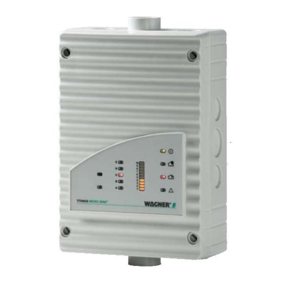
WAGNER Titanus Micro-Sens Technical Manual (238 pages)
Air sampling smoke detection system
Brand:
WAGNER
| Category:
Smoke Alarm
| Size: 5.44 MB
Table of Contents
Table of Contents
5
1 General
13
Introduction
13
Safety Information
13
Guarantee
14
Copyright
14
Packaging
14
Disposal
15
2 Product Description
17
Characteristics of the TITANUS MICRO·SENS® Aspirating Smoke
17
Areas of Application
20
3 Technical Description
25
System Description
25
Function
26
TITANUS MICRO·SENS ® and Accessories
30
Overview
30
Air Sampling Smoke Detection System
31
Detector Box
33
Diagnostics Tool
37
Network Modules
38
Remote Displays
40
Reaction Indicator
41
Pipe System
42
Overview
42
Aspiration Apertures for Room Monitoring
44
Aspiration Reduction Films
44
Aspiration Reduction Clips
45
Ceiling Duct for Concealed Mounting
46
Air Filters for Dusty Areas
48
Air Return for Pressure Differences and Air Pollution
51
Noise Suppressor
52
Steam Trap for Humid Areas
53
4 Technical Data
55
5 Titanus Micro·sens
55
Accessories TITANUS MICRO·SENS
58
Pipe System - TITANUS MICRO·SENS
60
Design
61
General
61
Regulations
62
Pipe Systems
62
Air Flow Monitoring
66
Sensitivity
68
Design Limits
69
Project Planning
70
Project Planning Guidelines
70
Determining the Necessary Accessories
70
Pipe Accessories
71
Sensitivity and Pipeline Project Planning
71
Pipeline Project Planning with Pipe Accessories
71
Aperture Diameter
76
Special Project Planning
78
Project Planning for Individual Aperture Monitoring
78
I-Pipe System
78
U-Pipe System
79
M-Pipe System
81
Double-U-Pipe System
82
Simplified Pipe Design
84
I-Pipe System
84
U-Pipe System
85
M-Pipe System
86
Double U-Pipe System
87
Project Planning with Branch Pipe
88
Project Design for Forced Air Flow
91
Project Design with Air Sampling Hose
95
Project Planning with Air Return
96
Power Supply
98
6 Installation
101
General
101
Installation Site
102
Fitting the TITANUS
102
Connecting the Air Sampling Pipe
104
Incorporation and Electrical Connection of Additional Modules
106
Connection to FAS, with Reset Button
109
Incorporating the Reset Board
110
Connection to a FAS, with Reset Board
113
Incorporating the Reset and Isolating Button Board
114
Function Switching Plan, Reset and Isolating Button Board
115
Incorporating the Relay Board
116
Function Switching Plan, Relay Board
118
Function Switching Plan, Relay Board
119
TITANUS MICRO·SENS ® in the Network
120
Installing the Network Module in the TITANUS MICRO·SENS
120
Connecting the Network Module to the TITANUS MICRO·SENS
123
Remote Displays
124
Connecting the Remote Displays to TITANUS MICRO·SENS
124
Parallel Display Housing
125
Electrical Connection
126
Reaction Indicator
128
Addressing the Reaction Indicators
128
Connecting the Reaction Indicator to the TITANUS MICRO·SENS
130
Inserting the Detection Unit in the Device Base Unit
131
Settings
132
Detection Unit
132
Setting Reaction Sensitivity
133
Delay Time for Triggering the Alarm
134
Threshold for Air Flow Monitoring
134
Delay Time for Air Flow Fault
135
Action-Alarm Threshold
135
Fault Display
136
Dynamic Air Flow
136
Room·ident
136
Logic·sens
137
Fire Alarm Threshold after ROOM·IDENT
137
Setting the Fan Voltage
137
Inputting the Current Air Pressure
138
Inputting Height above Normal Sea Level (NN)
138
Data Logging
139
7 Installation Pipe System
141
General Assembly
141
Mounting Pipe System
141
Mounting Air Sampling Hose
143
Linear Expansion of the Pipe System
145
Patented Air Sampling Points
147
Ceiling Lead through
149
Ceilings Feed-Through for False Ceiling
149
Other Ceilings Feed-Through
150
Monitoring in Forced Air Flow Systems (Ventilation or Climatic Applications)
152
Detection at Air Inlets/Outlets
152
Detection in Bypass Systems
153
Filter
154
Installation of Air Filter, Type LF-AD-X
154
Mounting of the Special Filter Type SF-400/650
155
Air Return
157
Noise Suppressor
158
3-Way Ball Valve
159
Steam Trap
161
Steam Trap Type KA
161
Steam Trap Type
162
Test Adapter
163
8 Commissioning
165
Commissioning the Detection Unit
165
Plug and Play Commissioning
166
Commissioning with the Diagnostics Tool
166
Installing Diagnostics Software
168
Air Flow Sensor Adjustment
170
Air Pressure-Independent Adjustment
171
Air Pressure-Dependent Adjustment
171
Testing the Detection Unit and Alarm Forwarding
173
Testing Air Flow Monitoring
174
Testing Fault Forwarding
175
Testing the Air Flow Sensor Analysis Function
175
Preparations for Function Testing
176
Carrying out Function Testing
178
Commissioning Fire Seat Location
181
Commissioning the Reaction Indicators
185
9 Maintenance
187
Visual Check
187
Testing Detector and Alarm Forwarding
187
Testing Pipe System
188
Exchanging the Detection Unit
189
Exchanging the Air Filter for the Device Base
190
Changing the Filter on the Type LF-AD-X Air Filter
191
Changing the Filter on the SF 400/650 Special Filter
193
Pipe System Blow through Process
195
Related Products
WAGNER TITANUS
WAGNER TITANIUS TOP-SENS
WAGNER TITANUS PRO-SENS
WAGNER TITANUS PRO-SENS SL
WAGNER Tiger
Wagner Tiger 72-300
WAGNER TITANUS SUPER-SENS
WAGNER TITANUS TOP-SENS
WAGNER TempSpray-H226
WAGNER TempSpray-H426
WAGNER Categories
Paint Sprayer
Lantern
Power Tool
Water Pump
Measuring Instruments
More WAGNER Manuals