beautypg.com
Manuals
Brands
WAGO Manuals
Control Unit
750-632
WAGO 750-632 Manuals
Manuals and User Guides for WAGO 750-632. We have
2
WAGO 750-632 manuals available for free PDF download: Manual
WAGO 750-632 Manual (154 pages)
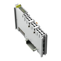
Proportional Valve Module WAGO I/O System 750/753
Brand:
WAGO
| Category:
Control Unit
| Size: 10.47 MB
Table of Contents
Table of Contents
3
Table of Contents
5
Notes about this Documentation
7
Copyright
7
Table 1: Versions
7
Validity of this Documentation
7
Symbols
8
Number Notation
10
Font Conventions
10
Table 2: Number Notation
10
Table 3: Font Conventions
10
Personnel Qualifications
11
Use of the 750 Series in Compliance with Underlying Provisions
11
Legal Bases
11
Subject to Changes
11
Important Notes
11
Technical Condition of Specified Devices
12
Disposal
12
2.1.4.1.1 Electrical and Electronic Equipment
12
2.1.4.1.2 Packaging
13
Safety Advice (Precautions)
14
Technology of Proportional Valves
17
Figure 1: Information Flow in the Proportional Hydraulics
17
Device Description
18
Table 4: Compatibility List 750-632
20
Figure 2: View
21
Table 5: Legend for Figure "View
21
View
21
Connectors
22
Data Contacts/Local Bus
22
Figure 3: Data Contacts
22
Power Jumper Contacts/Field Supply
23
Figure 4: Power Jumper Contacts
23
Table 6: Legend for Figure "Power Jumper Contacts
23
Table 7: Legend for the "Push-In CAGE CLAMP ® Connectors
24
Push-In CAGE CLAMP ® Connectors
24
Figure 5: Push-In CAGE CLAMP ® Connectors 750-632
24
Push-In CAGE CLAMP ® Connectors 750-632
24
Push-In CAGE CLAMP ® Connectors 750-632/000-100
25
Figure 6: Push-In CAGE CLAMP ® Connectors 750-632/000-100
25
Table 8: Legend for the "Push-In CAGE CLAMP ® Connectors
25
Display Elements
26
Figure 7: Display Elements
26
Table 9: Legend for Figure "Display Elements
26
Figure 8: Schematic Diagram 750-632
28
Schematic Diagram 750-632
28
Schematic Diagram
28
Schematic Diagram 750-632/000-100
29
Figure 9: Schematic Diagram 750-632/000-100
29
Table 10: Technical Data - Device Data
30
Technical Data
30
Table 12: Technical Data - Communication
30
Table 11: Technical Data - Supply
30
Table 13: Technical Data - Inputs
30
Inputs
30
Communication
30
Power Supply
30
Device Data
30
Table 14: Technical Data - Outputs
31
Table 15: Different Electrical Information in Accordance with ATEX/IECEX
31
Outputs
31
Wiring
32
Environmental Conditions
32
Table 16: Technical Data - Wiring
32
Table 17: Technical Data - Ambient Conditions
32
Approvals
33
Standards and Guidelines
34
Table 18: Operating Mode with One Valve
35
Function Description
35
Operating Mode with One Valve
35
Operating Modes
35
Operating Mode with Two Valves
36
Table 19: Operating Mode with Two Valves
36
Specifying the Setpoint Value
37
Specifying the Setpoint Value: Operating Mode with One Valve
37
Table 20: Operating Mode with One Valve
37
Table 22: Operating Mode with Two Valves
38
Table 21: Operating Mode with Two Valves
38
Specifying the Setpoint Value: Operating Mode with Two Valves, Coil Control: Two Coils, Unidirectional (3-Wire)
38
Specifying Setpoint Value: Operating Mode with Two Valves
38
Functions for the Setpoint Value Control
39
Automatic Mode
39
Figure 10: Automatic Mode
39
Table 23: Automatic Mode
39
Jog Mode
40
Figure 11: Jog Mode
40
Table 24: Jog Mode
40
Table 25: Tip Mode
41
Tip Mode
41
Figure 12: Tip Mode
41
Table 26: "HOLD" Function
42
Hold
42
Figure 13: "HOLD" Function
42
Stop
43
Figure 14: "STOP" Function Via Digital Inputs
43
End Stop Behavior
44
End Stop Behavior in "Automatic Mode
44
Table 27: "STOP" Function Via Digital Inputs
44
Table 28: End Stop Behavior
44
Table 29: Approach End Stop Value
45
Figure 15: Approach End Stop Value
45
5.3.6.1.1 Approach End Stop Value
45
Hold Current Value ("Freeze")
47
Figure 16: Hold Current Value ("Freeze")
47
Table 30: Hold Current Value ("Freeze")
47
End Stop Behavior in "JOG Mode" and "TIP Mode
48
5.3.6.2.1 Approach End Stop Value
48
Figure 17: Approach End Stop Value
48
Table 31: Approach End Stop Value
49
Table 32: Hold Current Value ("Freeze")
50
Figure 18: Hold Current Value ("Freeze")
50
Hold Current Value ("Freeze")
50
Substitute Value Strategy
51
Approach Substitute Value
51
Leave Substitute Value Strategy after an Error
51
Manual Mode in Case of Error (Emergency Operation)
52
Digital Inputs
53
Generating Setpoint Values
54
Overview of the Internal Information Flow
54
Table 33: Overview of the Internal Information Flow
54
Figure 19: Overview of the Internal Information Flow
55
Table 34: Legend - Overview of the Internal Information Flow
55
Function Block: Ramp Generator
56
Figure 20: Ramp Generator
56
Figure 21: Start up Ramp 100% in 1 Ms
57
Figure 22: Start up Ramp 100% in 100 Ms
57
Table 35: Resolution of the Nominal Current
57
Table 36: Correlation: Resolution - Time
57
Figure 24: Function Block: Linearization
58
Table 37: Reference Values for Ramps
58
Figure 23: Start up Ramp 100% in 10,000 Ms
58
Function Block: Linearization
58
Function Block: Valve Adjustment
59
Definition of "Overlap
59
Figure 25: Negative Overlap
59
Figure 26: Zero Overlap
59
Figure 27: Positive Overlap
60
Table 38: Types of Overlap
60
Exemplary Depiction of the Characteristic Curve Compensation
61
Function Block: Nominal Current
61
Figure 28: Characteristic Curve Compensation
61
Table 39: Function Block: Nominal Current
62
Function Block: Dither Generator
62
Current Outputs for Valve Coils
64
Figure 29: Current Carrying Capacity Curve
64
Process Image
65
All Fieldbuses (Except PROFIBUS and PROFINET)
65
Operating Mode with One Valve
65
Operating Mode with Two Valves
65
Table 40: Process Image
65
Table 41: Process Image
65
Table 42: Process Image
66
Table 44: Control Byte C0
66
Table 43: Process Image
66
Operating Mode with One Valve
66
Control and Status Bytes
66
Operating Mode with Two Valves
66
PROFIBUS and PROFINET
66
Table 45: Status Byte S0
67
Table 46: Control Byte C1 or C2
68
Table 47: Locking the Bits M_UP and M_DOWN
68
Table 48: Status Byte S1
69
Table 49: Status Byte S2
69
Table 50: Representation of Target and Actual Values
70
Representation of Target and Actual Values
70
Mounting
71
Mounting Sequence
72
Inserting and Removing Devices
72
Inserting the I/O Module
72
Removing the I/O Module
73
Figure 30: Inserting I/O Module (Example)
73
Figure 31: Snap the I/O Module into Place (Example)
73
Figure 32: Removing the I/O Module (Example)
74
Figure 33: Connecting a Conductor to a Push-In CAGE CLAMP
75
Connecting a Conductor to the Push-In CAGE CLAMP
75
Connect Devices
75
Table 51: Legend for Figure "Power Supply, Marine Applications
76
Power Supply for Marine Applications
76
Figure 34: Power Supply, Marine Applications
76
Figure 35: Connection Example 1: 2 Valves (2-Wire)
77
Figure 36: Connection Example 2: 1 Valve (4-Wire)
77
Connection Examples 750-632
77
Connection Example 2: 1 Valve (4-Wire)
77
Connection Example 1: 2 Valves (2-Wire)
77
Connection Example 3: 1 Valve (3-Wire)
78
Figure 37: Connection Example 3: 1 Valve (3-Wire)
78
Connection Examples 750-632/000-100
79
Connection Example 1: 2 Valves (3-Wire)
79
Figure 38: Connection Example 1: 2 Valves (3-Wire)
79
Figure 39: Connection Example 2: 1 Valve (3-Wire), 1 Valve (2-Wire)
79
Connection Example 2: 1 Valve (3-Wire), 1 Valve (2-Wire)
79
Commissioning
81
Configuration and Parameterization with WAGO-I/O-CHECK
81
Figure 40: WAGO-I/O-CHECK User Interface
82
Parameterization Dialog
83
Figure 41: Parameterization Dialog for the I/O Module
83
Table 52: Legend for the "Parameterization Dialog for the I/O Module
83
Table 53: Buttons on the Main Menu
84
Toolbar
84
Figure 42: Buttons in the Main Menu
84
9.1.1.1.1 Main Menu
84
9.1.1.1.2 Application Menu
86
Figure 43: Buttons in the Application Menu
86
Table 54: Buttons in the Application Menu
86
Navigation Area
87
Application Area
87
Table 55: "Operating Mode" - Settings Menu Item
88
Figure 44: "Operation Mode" Menu Item
88
9.1.1.3.1 "Operation Mode" Menu Item
88
Figure 45: Operation Mode" Menu Item (750-632/000-100)
89
Table 56: "Operating Mode" - Advanced Setting Menu Item
89
9.1.1.3.2 "Module Parameters" Menu Item
90
Figure 46: "Module Parameters" Menu Item
90
Table 57: "Module Parameters" Menu Item
90
9.1.1.3.3 "Digital Inputs" Menu Item
92
Figure 47: "Digital Inputs" Menu Item
92
Table 58: "Digital Inputs" Menu Item
92
9.1.1.3.4 "Ramp Settings" Menu Item
93
Figure 48: "Ramp Settings" Menu Item
93
Table 59: "Ramp Settings" Menu Item
94
9.1.1.3.5 "Dither Generator" Menu Item
95
Figure 49: "Dither Generator" Menu Item
95
Table 60: "Dither Generator" Menu Item
95
9.1.1.3.6 "Valve Adjustment" Menu Item
96
Figure 50: "Valve Adjustment" Menu Item
96
Table 61: "Valve Adjustment" Menu Item
96
9.1.1.3.7 "Linearization" Menu Item
97
Figure 51: "Linearization" Menu Item
97
Table 62: "Linearization" Menu Item
97
Table 63: "Position" Menu Item
98
Figure 52: "Position" Menu Item
98
9.1.1.3.8 "Position" Menu Item
98
Diagnostics Area
99
State Bar
99
Diagnostics
100
Range Overrun by the Setpoint Value
100
Range Overrun by the Current Controller
100
Interference at the Local Bus
100
Changing the Configuration
100
Figure 53: Response During Undervoltage
101
Undervoltage
101
Undervoltage, Short Circuit, Wire Break, Overtemperature
101
Short Circuit
102
Wire Break
102
Overtemperature
102
Figure 54: Response During Short Circuit
102
Switching Outputs Back on
103
Diagnostics Via Leds
104
Table 64: Diagnostics Via Leds
104
Table 65: Diagnostics Via Process Image
105
Diagnostics Via Process Image
105
Appendix
106
Mailbox 2.0 Transmission Method
106
Message
106
Figure 55: Communication Via Mailbox 2.0
106
Figure 56: Simple Header (Structure)
106
Transmission Channel
107
The Handshake Byte
107
Figure 57: Extended Header (Structure)
107
Figure 58: Structure of the Handshake Byte
108
Figure 59: Use of the Handshake Byte
108
Synchronization
108
Communication Phases
108
11.1.3.1.1 Mailbox Commands
109
11.1.3.1.2 Acknowledgement
109
Table 66: Commands
109
Table 67: Acknowledgement
109
11.1.3.1.3 Signaling
110
Figure 60: Structure of the Handshake Byte
110
Table 68: Signaling
110
Figure 61: Finite Automation
111
Data Exchange
111
11.1.3.1.4 Finite Automation
111
11.1.3.2.1 Example
113
Figure 62: : Example of Send Operation
113
Protocols Supported by Mailbox 2.0
114
Protocol 0X80 (Parameter Access)
114
Table 69: Protocol 0X80, Description of Services
114
Table 70: Protocol 0X80, PDU Structure
114
Protocol 0X81 (Diagnostics)
115
Table 71: Protocol 0X80, Structure of Pdus, Legend
115
Table 72: Protocol 0X81, Description of Services
115
Table 73: Protocol 0X81, PDU Structure
115
Table 74: Protocol 0X81, Structure of Pdus, Legend
116
Diagnostics Via Mailbox
117
Channel Error
117
Table 75: Channel Errors
117
General Errors
119
Table 76: General Errors
119
Communication Errors
120
Table 77: Channel Errors
120
Table 78: Key: Diagnostics Via Mailbox
121
Table 80: Parameters, Table 30 (Valve Configuration)
122
Table 79: Parameter, Reference, List of Tables
122
Channel-Independent Parameters
122
Parameter, Reference
122
Table 81: Parameters, Table 31 (Status)
123
Table 82: Parameter, Table 32 (Module Monitoring)
123
Tables 33, 34 (DI1, DI2)
124
Table 83: Parameters, Table 33 (DI1)
124
Table
125
Table 84: Parameter, Table 32 (Module Monitoring)
125
Channel-Dependent Parameters
126
Tables 50, 51 (Process Data Handling, Valve 1, Valve 2)
126
Table 85: Parameters, Table 50 (Process Data Handling, Valve 1)
126
Tables 52, 53 (Output Stage, Valve 1, Valve 2)
127
Table 86: Parameters, Table 52 (Output Stage, Valve 1)
127
Table 87: Parameters, Table 54 (Status, Valve 1)
128
Tables 54, 55 (Status Valve 1, Valve 2)
128
Tables 56, 57 (Ramp Generator, Valve 1, Valve 2)
129
Table 88: Parameters, Table 56 (Ramp Generator, Valve 1)
129
Tables 58, 59 (Characteristic Curve Adjustment, Valve 1, Valve 2)
130
Table 89: Parameters, Table 58 (Characteristic Curve Adjustment, Valve 1)
130
Tables 60, 61 (Valve Adjustment, Valve 1, Valve 2)
132
Table 90: Parameters, Table 60 (Valve Adjustment, Valve 1)
132
Table 91: Parameters, Table 62 (Dithering, Valve 1)
133
Table 93: Parameters, Table 72 (Process Variables, Valve 1)
134
Tables 68, 69 (Current Controller, Valve 1, Valve 2)
134
Table 92: Parameters, Table 68 (Current Controller, Valve 1)
134
Tables 72, 73 (Process Variables, Valve 1, Valve 2)
134
Number Representation
135
Setpoint Value
135
Actual Value
135
Table 94: Process Values - Setpoint Value
135
Table 95: Process Values - Actual Value
136
Use in Hazardous Environments
137
Figure 64: Text Detail - Marking Example According to ATEX and Iecex
138
Marking for Europe According to ATEX and Iecex
138
Marking Configuration Examples
138
Figure 63: Marking Example According to ATEX and Iecex
138
Table 96: Description of Marking Example According to ATEX and Iecex
139
Figure 65: Marking Example for Approved I/O Module Ex I According to
140
Figure 66: Text Detail - Marking Example for Approved I/O Moduleex I
140
Table 97: Description of Marking Example for Approved I/O Module Ex I
141
Marking for the United States of America (NEC) and Canada (CEC)
142
Figure 67: Marking Example According to NEC
142
Figure 68: Text Detail - Marking Example According to NEC 500
142
Table 98: Description of Marking Example According to NEC 500
142
Table 100: Description of Marking Example for Approved I/O Module Ex I
143
Figure 69: Text Detail - Marking Example for Approved I/O Module Ex I
143
Table 99: Description of Marking Example for Approved I/O Module Ex I
143
Figure 70: Text Detail - Marking Example for Approved I/O Module Ex I
143
Figure 71: Text Detail - Marking Example for Approved I/O Module Ex I
144
Table 101: Description of Marking Example for Approved I/O Module Ex I
144
Installation Regulations
145
Special Notes Including Explosion Protection
145
Special Notes Regarding ANSI/ISA Ex
147
List of Figures
148
List of Tables
150
WAGO 750-632 Manual (152 pages)
Proportional Valve Module For WAGO-I/O-SYSTEM 750
Brand:
WAGO
| Category:
Control Unit
| Size: 7.19 MB
Table of Contents
Table of Contents
5
Table of Contents
3
1 Notes about this Documentation
7
Validity of this Documentation
7
Copyright
7
Table 1: Versions
7
Symbols
8
Number Notation
10
Font Conventions
10
Table 2: Number Notation
10
Table 3: Font Conventions
10
2 Important Notes
11
Legal Bases
11
Subject to Changes
11
Personnel Qualifications
11
Use of the WAGO-I/O-SYSTEM 750 in Compliance with Underlying Provisions
11
Technical Condition of Specified Devices
12
Safety Advice (Precautions)
13
3 Technology of Proportional Valves
15
Figure 1: Information Flow in the Proportional Hydraulics
15
4 Device Description
16
Table 4: Compatibility List 750-632
18
View
19
Figure 2: View
19
Table 5: Legend for Figure "View
19
Connectors
20
Data Contacts/Internal Bus
20
Figure 3: Data Contacts
20
Power Jumper Contacts/Field Supply
21
Figure 4: Power Jumper Contacts
21
Table 6: Legend for Figure "Power Jumper Contacts
21
Push-In CAGE CLAMP ® Connectors
22
Push-In CAGE CLAMP ® Connectors 750-632
22
Figure 5: Push-In CAGE CLAMP ® Connectors 750-632
22
Push-In CAGE CLAMP ® Connectors 750-632/000-100
23
Figure 6: Push-In CAGE CLAMP ® Connectors 750-632/000-100
23
Table 8: Legend for the "Push-In CAGE CLAMP ® Connectors
23
Display Elements
24
Figure 7: Display Elements
24
Table 9: Legend for Figure "Display Elements
24
Schematic Diagram
26
Schematic Diagram 750-632
26
Figure 8: Schematic Diagram 750-632
26
Schematic Diagram 750-632/000-100
27
Figure 9: Schematic Diagram 750-632/000-100
27
Technical Data
28
Device Data
28
Power Supply
28
Communication
28
Inputs
28
Table 10: Technical Data - Device Data
28
Table 11: Technical Data - Supply
28
Table 12: Technical Data - Communication
28
Table 13: Technical Data - Inputs
28
Outputs
29
Table 14: Technical Data - Outputs
29
Table 15: Different Electrical Information in Accordance with ATEX/IECEX-Certificate
29
Wiring
30
Environmental Conditions
30
Table 16: Technical Data - Wiring
30
Table 17: Technical Data - Ambient Conditions
30
Approvals
31
Standards and Guidelines
32
5 Function Description
33
Operating Modes
33
Operating Mode with One Valve
33
Table 18: Operating Mode with One Valve
33
Operating Mode with Two Valves
34
Table 19: Operating Mode with Two Valves
34
Specifying the Setpoint Value
35
Specifying the Setpoint Value: Operating Mode with One Valve
35
Table 20: Operating Mode with One Valve
35
Specifying Setpoint Value: Operating Mode with Two Valves
36
Specifying the Setpoint Value: Operating Mode with Two Valves, Coil Control: Two Coils, Unidirectional (3-Wire)
36
Table 21: Operating Mode with Two Valves
36
Table 22: Operating Mode with Two Valves
36
Functions for the Setpoint Value Control
37
Automatic Mode
37
Figure 10: Automatic Mode
37
Table 23: Automatic Mode
37
Jog Mode
38
Figure 11: Jog Mode
38
Table 24: Jog Mode
38
Tip Mode
39
Figure 12: Tip Mode
39
Table 25: Tip Mode
39
Hold
40
Figure 13: "HOLD" Function
40
Table 26: "HOLD" Function
40
Stop
41
Figure 14: "STOP" Function Via Digital Inputs
41
End Stop Behavior
42
End Stop Behavior in "Automatic Mode
42
Table 27: "STOP" Function Via Digital Inputs
42
Table 28: End Stop Behavior
42
5.3.6.1.1 Approach End Stop Value
43
Figure 15: Approach End Stop Value
43
Table 29: Approach End Stop Value
43
Hold Current Value ("Freeze")
45
Figure 16: Hold Current Value ("Freeze")
45
Table 30: Hold Current Value ("Freeze")
45
End Stop Behavior in "JOG Mode" and "TIP Mode
46
5.3.6.2.1 Approach End Stop Value
46
Figure 17: Approach End Stop Value
46
Table 31: Approach End Stop Value
47
Hold Current Value ("Freeze")
48
Figure 18: Hold Current Value ("Freeze")
48
Table 32: Hold Current Value ("Freeze")
48
Substitute Value Strategy
49
Approach Substitute Value
49
Leave Substitute Value Strategy after an Error
49
Manual Mode in Case of Error (Emergency Operation)
50
Digital Inputs
51
Generating Setpoint Values
52
Overview of the Internal Information Flow
52
Table 33: Overview of the Internal Information Flow
52
Figure 19: Overview of the Internal Information Flow
53
Table 34: Legend - Overview of the Internal Information Flow
53
Function Block: Ramp Generator
54
Figure 20: Ramp Generator
54
Figure 21: Start up Ramp 100% in 1 Ms
55
Figure 22: Start up Ramp 100% in 100 Ms
55
Table 35: Resolution of the Nominal Current
55
Table 36: Correlation: Resolution - Time
55
Function Block: Linearization
56
Figure 23: Start up Ramp 100% in 10,000 Ms
56
Figure 24: Function Block: Linearization
56
Table 37: Reference Values for Ramps
56
Function Block: Valve Adjustment
57
Definition of "Overlap
57
Figure 25: Negative Overlap
57
Figure 26: Zero Overlap
57
Figure 27: Positive Overlap
58
Table 38: Types of Overlap
58
Exemplary Depiction of the Characteristic Curve Compensation
59
Function Block: Nominal Current
59
Figure 28: Characteristic Curve Compensation
59
Function Block: Dither Generator
60
Table 39: Function Block: Nominal Current
60
Current Outputs for Valve Coils
62
Figure 29: Current Carrying Capacity Curve
62
6 Process Image
63
All Fieldbuses (Except PROFIBUS and PROFINET)
63
Operating Mode with One Valve
63
Operating Mode with Two Valves
63
Table 40: Process Image
63
Table 41: Process Image
63
PROFIBUS and PROFINET
64
Operating Mode with One Valve
64
Operating Mode with Two Valves
64
Control and Status Bytes
64
Table 42: Process Image
64
Table 43: Process Image
64
Table 44: Control Byte C0
64
Table 45: Status Byte S0
65
Table 46: Control Byte C1 or C2
65
Table 47: Locking the Bits M_UP and M_DOWN
66
Table 48: Status Byte S1
66
Table 49: Status Byte S2
66
Representation of Target and Actual Values
67
Table 50: Representation of Target and Actual Values
67
7 Mounting
68
Mounting Sequence
68
Inserting and Removing Devices
69
Inserting the I/O Module
69
Figure 30: Insert I/O Module (Example)
69
Figure 31: Snap the I/O Module into Place (Example)
69
Removing the I/O Module
70
Figure 32: Removing the I/O Module (Example)
70
8 Connect Devices
71
Connecting a Conductor to the CAGE CLAMP
71
Figure 33: Connecting a Conductor to a CAGE CLAMP
71
Power Supply for Marine Applications
72
Figure 34: Power Supply, Marine Applications
72
Table 51: Legend for Figure "Power Supply, Marine Applications
72
Connection Examples 750-632
73
Connection Example 1: 2 Valves (2-Wire)
73
Connection Example 2: 1 Valve (4-Wire)
73
Figure 35: Connection Example 1: 2 Valves (2-Wire)
73
Figure 36: Connection Example 2: 1 Valve (4-Wire)
73
Connection Example 3: 1 Valve (3-Wire)
74
Figure 37: Connection Example 3: 1 Valve (3-Wire)
74
Connection Examples 750-632/000-100
75
Connection Example 1: 2 Valves (3-Wire)
75
Connection Example 2: 1 Valve (3-Wire), 1 Valve (2-Wire)
75
Figure 38: Connection Example 1: 2 Valves (3-Wire)
75
Figure 39: Connection Example 2: 1 Valve (3-Wire), 1 Valve (2-Wire)
75
9 Commissioning
77
Configuration and Parameterization with WAGO-I/O-CHECK
77
Figure 40: WAGO-I/O-CHECK User Interface
78
Parameterization Dialog
79
Figure 41: Parameterization Dialog for the I/O Module
79
Table 52: Legend for the "Parameterization Dialog for the I/O Module
79
Toolbar
80
9.1.1.1.1 Main Menu
81
Figure 42: Buttons in the Main Menu
81
Table 53: Buttons on the Main Menu
81
9.1.1.1.2 Application Menu
82
Figure 43: Buttons in the Application Menu
82
Table 54: Buttons in the Application Menu
82
Navigation Area
83
Application Area
83
9.1.1.3.1 "Operation Mode" Menu Item
84
Figure 44: "Operation Mode" Menu Item
84
Table 55: "Operating Mode" - Settings Menu Item
84
Figure 45: Operation Mode" Menu Item (750-632/000-100)
85
Table 56: "Operating Mode" - Advanced Setting Menu Item
85
9.1.1.3.2 "Module Parameters" Menu Item
86
Figure 46: "Module Parameters" Menu Item
86
Table 57: "Module Parameters" Menu Item
86
9.1.1.3.3 "Digital Inputs" Menu Item
88
Figure 47: "Digital Inputs" Menu Item
88
Table 58: "Digital Inputs" Menu Item
88
9.1.1.3.4 "Ramp Settings" Menu Item
89
Figure 48: "Ramp Settings" Menu Item
89
Table 59: "Ramp Settings" Menu Item
90
9.1.1.3.5 "Dither Generator" Menu Item
91
Figure 49: "Dither Generator" Menu Item
91
Table 60: "Dither Generator" Menu Item
91
9.1.1.3.6 "Valve Adjustment" Menu Item
92
Figure 50: "Valve Adjustment" Menu Item
92
Table 61: "Valve Adjustment" Menu Item
92
9.1.1.3.7 "Linearization" Menu Item
93
Figure 51: "Linearization" Menu Item
93
Table 62: "Linearization" Menu Item
93
9.1.1.3.8 "Position" Menu Item
94
Figure 52: "Position" Menu Item
94
Table 63: "Position" Menu Item
94
Diagnostics Area
95
State Bar
95
10 Diagnostics
96
Range Overrun by the Setpoint Value
96
Range Overrun by the Current Controller
96
Interference at the Internal Data Bus
96
Changing the Configuration
96
Undervoltage, Short Circuit, Wire Break, Overtemperature
97
Undervoltage
97
Figure 53: Response During Undervoltage
97
Short Circuit
98
Wire Break
98
Overtemperature
98
Figure 54: Response During Short Circuit
98
Switching Outputs Back on
99
Diagnostics Via Leds
100
Table 64: Diagnostics Via Leds
100
Diagnostics Via Process Image
101
Table 65: Diagnostics Via Process Image
101
11 Appendix
102
Mailbox 2.0 Transmission Method
102
Message
102
Figure 55: Communication Via Mailbox 2.0
102
Transmission Channel
103
Table 66: Structure of the Simple Header
103
Table 67: Structure of the Extended Header
103
The Handshake Byte
104
Figure 56: Use of the Handshake Byte
104
Table 68: Structure of the Handshake Byte
104
Communication Phases
105
Synchronization
105
11.1.3.1.1 Mailbox Commands
105
Table 69: Commands
105
11.1.3.1.2 Acknowledgement
106
11.1.3.1.3 Signaling
106
Table 70: Acknowledgement
106
Table 71: Structure of the Handshake Byte
106
Table 72: Signaling
106
11.1.3.1.4 Finite Automation
107
Figure 57: Finite Automation
107
Data Exchange
108
11.1.3.2.1 Example
109
Figure 58: Example of Send Operation
109
Protocols Supported by Mailbox 2.0
110
Protocol 0X80 (Parameter Access)
110
Table 73: Protocol 0X80, Description of Services
110
Table 74: Protocol 0X80, PDU Structure
110
Protocol 0X81 (Diagnostics)
111
Table 75: Protocol 0X80, Structure of Pdus, Legend
111
Table 76: Protocol 0X81, Description of Services
111
Table 77: Protocol 0X81, PDU Structure
111
Table 78: Protocol 0X81, Structure of Pdus, Legend
112
Diagnostics Via Mailbox
113
Channel Error
113
Table 79: Channel Errors
113
General Errors
115
Table 80: General Errors
115
Communication Errors
116
Table 81: Channel Errors
117
Table 82: Key: Diagnostics Via Mailbox
117
Parameter, Reference
118
Channel-Independent Parameters
118
Table 83: Parameter, Reference, List of Tables
118
Table 84: Parameters, Table 30 (Valve Configuration)
118
Table 85: Parameters, Table 31 (Status)
119
Table 86: Parameter, Table 32 (Module Monitoring)
119
Tables 33, 34 (DI1, DI2)
120
Table 87: Parameters, Table 33 (DI1)
120
Table
121
Table 88: Parameter, Table 32 (Module Monitoring)
121
Channel-Dependent Parameters
122
Tables 50, 51 (Process Data Handling, Valve 1, Valve 2)
122
Table 89: Parameters, Table 50 (Process Data Handling, Valve 1)
122
Tables 52, 53 (Output Stage, Valve 1, Valve 2)
123
Table 90: Parameters, Table 52 (Output Stage, Valve 1)
123
Tables 54, 55 (Status Valve 1, Valve 2)
124
Table 91: Parameters, Table 54 (Status, Valve 1)
124
Tables 56, 57 (Ramp Generator, Valve 1, Valve 2)
125
Table 92: Parameters, Table 56 (Ramp Generator, Valve 1)
125
Tables 58, 59 (Characteristic Curve Adjustment, Valve 1, Valve 2)126
126
Table 93: Parameters, Table 58 (Characteristic Curve Adjustment, Valve 1)
126
Tables 60, 61 (Valve Adjustment, Valve 1, Valve 2)
128
Table 94: Parameters, Table 60 (Valve Adjustment, Valve 1)
128
Table 95: Parameters, Table 62 (Dithering, Valve 1)
129
Tables 68, 69 (Current Controller, Valve 1, Valve 2)
130
Tables 72, 73 (Process Variables, Valve 1, Valve 2)
130
Table 96: Parameters, Table 68 (Current Controller, Valve 1)
130
Table 97: Parameters, Table 72 (Process Variables, Valve 1)
130
Number Representation
131
Setpoint Value
131
Actual Value
131
Table 98: Process Values - Setpoint Value
131
Table 99: Process Values - Actual Value
132
12 Use in Hazardous Environments
133
Marking Configuration Examples
134
Marking for Europe According to ATEX and IEC-Ex
134
Figure 59: Side Marking Example for Approved I/O Modules According to ATEX and Iecex
134
Figure 60: Text Detail - Marking Example for Approved I/O Modules According to ATEX and Iecex
135
Table 100: Description of Marking Example for Approved I/O Modules According to ATEX and Iecex
136
Figure 61: Side Marking Example for Approved Ex I I/O Modules According to ATEX and Iecex
137
Figure 62: Text Detail - Marking Example for Approved Ex I I/O Modules According to ATEX and Iecex
137
Table 101: Description of Marking Example for Approved Ex I I/O Modules According to ATEX and Iecex
139
Marking for America According to NEC 500
140
Figure 63: Side Marking Example for I/O Modules According to NEC 500
140
Figure 64: Text Detail - Marking Example for Approved I/O Modules According
140
Table 102: Description of Marking Example for Approved I/O Modules
140
Installation Regulations
141
Special Conditions for Safe Use (TÜV 14 ATEX 148929 X)
142
Special Conditions for Safe Use (ATEX Certificate TÜV 12 ATEX 106032 X)
143
Special Conditions for Safe Use (IEC-Ex Certificate TUN 14.0035X)144
144
Special Conditions for Safe Use (IEC-Ex Certificate Iecex TUN 12.0039 X)
145
Special Conditions for Safe Use According to ANSI/ISA
146
List of Figures
147
List of Tables
149
Related Products
WAGO 750-638
WAGO 750-637
WAGO 750-637/000-001
WAGO 750-637/000-002
WAGO 750-637/000-004
WAGO 750-633
WAGO 750-632/000-100
WAGO 750-624/040-00 Series
WAGO TECHDOCS 750-600/000-001
WAGO 750-624/020-002
WAGO Categories
I/O Systems
Control Unit
Power Supply
Switch
Controller
More WAGO Manuals