beautypg.com
Manuals
Brands
WAGO Manuals
I/O Systems
750-872/020-000
WAGO 750-872/020-000 Manuals
Manuals and User Guides for WAGO 750-872/020-000. We have
1
WAGO 750-872/020-000 manual available for free PDF download: Manual
WAGO 750-872/020-000 Manual (290 pages)
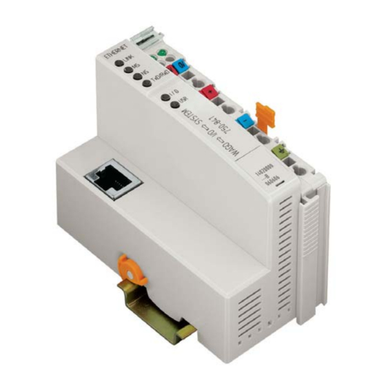
Modular I/O-System, Programmable Fieldbus Controller for Telecontrol Applications
Brand:
WAGO
| Category:
I/O Systems
| Size: 2.94 MB
Table of Contents
Table of Contents
3
1 Important Notes
9
Legal Principles
9
Copyright
9
Personnel Qualification
9
Conforming Use of Series 750
10
Technical Condition of the Devices
10
Standards and Regulations for Operating the 750 Series
10
Symbols
11
Safety Information
12
Font Conventions
13
Number Notation
13
Scope
14
Important Comments for Starting up
14
Abbreviation
14
2 The WAGO-I/O-SYSTEM 750
15
System Description
15
Technical Data
16
Manufacturing Number
22
Component Update
23
Storage, Assembly and Transport
23
Mechanical Setup
24
Installation Position
24
Total Expansion
24
Assembly Onto Carrier Rail
25
Carrier Rail Properties
25
WAGO DIN Rail
26
Spacing
26
Plugging and Removal of the Components
27
Assembly Sequence
28
Internal Bus/Data Contacts
29
Power Contacts
30
Wire Connection
31
Power Supply
32
Isolation
32
System Supply
33
Connection
33
Alignment
34
Field Supply
36
Connection
36
Fusing
37
Supplementary Power Supply Regulations
40
Supply Example
41
Power Supply Unit
42
Grounding
43
Grounding the DIN Rail
43
Framework Assembly
43
Insulated Assembly
43
Grounding Function
44
Grounding Protection
45
Shielding (Screening)
46
General
46
Bus Conductors
46
Signal Conductors
46
WAGO Shield (Screen) Connecting System
47
Assembly Guidelines/Standards
47
3 Fieldbus Controller
48
Fieldbus Controller 750-872/020-000
48
Description
48
Compatibility
49
Hardware
50
View
50
Device Supply
51
Fieldbus Connection
52
Display Elements
52
Configuration and Programming Interface
53
Operating Mode Switch
54
Hardware Address (MAC-ID)
55
Operating System
56
Start-Up
56
PLC Cycle
56
Process Image
58
General Structure
58
Example of a Process Input Image
60
Example of a Process Output Image
61
Process Data Architecture
62
Data Exchange
63
Memory Areas
64
Addressing
66
Addressing the I/O Modules
66
Address Range
66
Absolute Addresses
68
Data Exchange between Ethernet/Ip Master and I/O Modules
71
Data Exchange between PLC Functionality (CPU) and I/O Modules
72
Data Exchange between Master and PLC Functionality (CPU)
72
Example MODBUS/TCP Master and PLC Functionality (CPU)
73
Example of Use
74
Starting up a Fieldbus Node
75
Variation 1: Start up with the WAGO Ethernet Settings
75
Connecting PC and Fieldbus Node
75
Allocating the IP Address to the Fieldbus Node
76
Testing the Function of the Fieldbus Node
76
Variation 2:Starting up with the WAGO Bootp Server
77
Note the MAC-ID and Establish the Fieldbus Node
77
Connecting PC and Fieldbus Node
77
Determining IP Addresses
78
Allocating the IP Address to the Fieldbus Node
78
Wago-I/O-System
78
Testing the Function of the Fieldbus Node
81
Deactivating the Bootp Protocol
82
Transmission Mode Configuration
84
Programming the PFC with WAGO-I/O-PRO CAA
85
WAGO-I/O-PRO CAA Library Elements for ETHERNET
89
Restrictions in the Function Range
90
Some Basic Facts about IEC Tasks
92
Flowchart of an IEC Task
92
Overview of the most Important Task Priorities (Descending Priority)
93
System Events
94
IEC 61131-3-Program Transfer
95
Transmission Via the Serial Interface
96
Transmission by the Fieldbus
97
Information on the Web-Based Management System
98
Configuration of SNMP
106
Description of MIB II
106
System Group
107
Interface Group
107
Address Translation Group
108
IP Group
109
Iproute Table
110
Ipnettomediatable
110
ICMP Group
110
TCP Group
112
UDP Group
112
SNMP Group
113
EGP-Group
114
Traps
114
LED Display
115
Fieldbus Status
116
Node Status - Blink Code from the 'I/O' LED
117
Usr'-Led
124
Supply Voltage Status
125
Fault Behavior
125
Fieldbus Failure
125
Internal Bus Fault
126
Technical Data
127
4 Fieldbus Communication
129
Ethernet
129
General
129
Network Architecture - Principles and Regulations
130
Transmission Media
131
Network Topologies
133
Coupler Modules
136
Transmission Mode
136
Static Configuration of the Transmission Mode
137
Dynamic Configuration of the Transmission Mode
137
Errors Occurring When Configuring the Transmission Mode
137
Wago-I/O-System
137
Important Terms
138
Network Communication
140
Protocol Layer Model
140
Communication Protocols
142
Ethernet
143
Channel Access Method
143
IP-Protocol
144
Raw Ip
148
IP Multicast
148
TCP Protocol
148
Udp
149
Arp
149
Administration and Diagnosis Protocols
150
Bootp (Bootstrap Protocol)
150
HTTP (Hypertext Transfer Protocol)
151
DHCP (Dynamic Host Configuration Protocol)
152
DNS (Domain Name Systems)
153
SNTP-Client (Simple Network Time Protocol)
153
FTP-Server (File Transfer Protocol)
153
SMTP (Simple Mail Transfer Protocol)
155
Application Protocols
155
MODBUS Functions
156
General
156
Use of the MODBUS Functions
158
Description of the MODBUS Functions
159
Function Code FC1 (Read Coils)
160
Function Code FC2 (Read Input Discretes)
161
Function Code FC3 (Read Multiple Registers)
162
Function Code FC4 (Read Input Registers)
163
Function Code FC5 (Write Coil)
164
Function Code FC6 (Write Single Register)
165
Function Code FC11 (Get Comm Event Counter)
166
Function Code FC15 (Force Multiple Coils)
167
Function Code FC16 (Write Multiple Registers)
168
Function Code FC22 (Mask Write Register)
169
Function Code FC23 (Read/Write Multiple Registers)
170
MODBUS Register Mapping
171
Internal Variables
173
Description of the Internal Variables
174
Watchdog (Fieldbus Failure)
174
Watchdog Register
175
Diagnostic Functions
179
Configuration Functions
179
Firmware Information
183
Constant Registers
184
Ethernet/Ip (Ethernet/Industrial Protocol)
186
General
186
Characteristics of the Ethernet/Ip Protocol Software
187
Wago-I/O-System
187
Object Model
188
General
188
Classes
189
CIP Common Classes
189
WAGO Specific Classes
189
Explanations of the Object Description
190
Identity
191
Hex )
191
Message Router (02 Hex )
192
Assembly (04 Hex )
193
Static Assembly Instances
193
Port Class (F4 Hex )
196
TCP/IP Interface (F5 Hex )
197
Ethernet Link
198
Controller Configuration
198
Hex
198
Discrete Input Point (65 Hex )
200
Discrete Output Point (66 Hex )
201
Analog Input Point (67 Hex )
201
Analog Output Point (68 Hex )
202
Discrete Input Point Extended
202
Discrete Output Point Extended 1
202
Hex, 6D Hex, 71 Hex )
202
Analog Input Point Extended 1
202
Analog Output Point Extended 1
203
Module Configuration
203
Module Configuration Extended
203
Input Fieldbus Variable USINT (A0 )
203
Hex
203
Input Fieldbus Variable USINT Extended 1 (A1 Hex )
204
Input Fieldbus Variable USINT Extended 2 (A2 Hex )
204
Output Fieldbus Variable USINT
204
Hex )
204
Output Fieldbus Variable USINT Extended
205
Hex )
205
Output Fieldbus Variable USINT Extended 2 (A5 Hex )
205
Input Fieldbus Variable UINT
206
Hex )
206
Input Fieldbus Variable USINT Extended 1 (A7 Hex )
206
Output Fieldbus Variable UINT
206
Output Fieldbus Variable UINT Extended
207
Hex )
207
Input Fieldbus Variable UDINT (AA )
207
Input Fieldbus Variable UDINT Offset (AB )
207
Output Fieldbus Variable UDINT (AC )
208
Output Fieldbus Variable UDINT Offset (AD )
208
5 O Modules
209
Overview
209
Digital Input Modules
209
Wago-I/O-System
210
Digital Output Modules
211
Analog Input Modules
212
Analog Output Modules
214
Special Modules
215
System Modules
217
Process Data Architecture for MODBUS/TCP
218
Digital Input Modules
218
Digital Output Modules
220
Analog Input Modules
224
Analog Output Modules
225
Specialty Modules
226
System Modules
238
Process Data Architecture for Ethernet/Ip
239
Digital Input Modules
239
Digital Output Modules
241
Analog Input Modules
245
Analog Output Modules
247
Specialty Modules
248
System Modules
258
6 Application Examples
260
Test of MODBUS Protocol and Fieldbus Nodes
260
Visualization and Control Using SCADA Software
260
7 Use in Hazardous Environments
263
Foreword
263
Protective Measures
263
Classification Meeting CENELEC and IEC
263
Divisions
263
Explosion Protection Group
265
Unit Categories
266
Temperature Classes
267
Types of Ignition Protection
268
Classifications Meeting the NEC 500
269
Divisions
269
Explosion Protection Groups
269
Temperature Classes
270
Identification
271
For Europe
271
For America
272
Installation Regulations
273
8 Glossary
275
9 Literature List
287
10 Index
288
Wago-I/O-System
289
Related Products
WAGO 750-842
WAGO 750-8207
WAGO 750-860
WAGO 750-841
WAGO 750-830
WAGO 750-882
WAGO 750-8 Series
WAGO 750-871
WAGO 750-8210/040-000
WAGO LONWORKS 750-819
WAGO Categories
I/O Systems
Control Unit
Power Supply
Switch
Controller
More WAGO Manuals