beautypg.com
Manuals
Brands
YOKOGAWA Manuals
Inverter
FG400
YOKOGAWA FG400 Manuals
Manuals and User Guides for YOKOGAWA FG400. We have
2
YOKOGAWA FG400 manuals available for free PDF download: User Manual
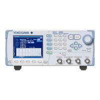
YOKOGAWA FG400 User Manual (180 pages)
Arbitrary/Function Generator
Brand:
YOKOGAWA
| Category:
Portable Generator
| Size: 4.83 MB
Table of Contents
Safety Precautions
6
Authorized Representative in the EEA
9
關於在台灣銷售
9
Table of Contents
11
Overview
15
Features
15
Operating Principles
16
Preparations before Use
18
Checking before Use
18
Installation
20
Grounding and Power Supply Connection
22
Calibration
23
Panels and I/O Terminals
24
Panel Components and Operations
24
Front Panel of FG410
24
Figure 3-1. Front Panel of FG410
24
Rear Panel of FG410
25
Figure 3-2. Rear Panel of FG410
25
Front Panel of FG420
26
Figure 3-3. Front Panel of FG420
26
Rear Panel of FG420
27
Figure 3-4. Rear Panel of FG420
27
I/O Terminals
28
Waveform Output (FCTN OUT)
29
Sync/Sub-Output (SYNC/SUB OUT)
29
External Modulation/Addition Input (MOD/ADD IN)
30
External Trigger Input (TRIG IN)
31
External 10 Mhz Frequency Reference Input (10 Mhz REF IN)
31
Frequency Reference Output (REF OUT)
32
Multi-I/O (MULTI I/O)
33
Figure 3-5. Multi-I/O Connector Pin Assignment
34
Cautions on Floating Ground Connection
36
Figure 3-6. Cautions on Floating Ground Connection for FG410
37
Figure 3-7. Cautions on Floating Ground Connection for FG420
38
Basic Operation
39
Power On/Off Switching and Restoration of Settings
39
Power On/Off Switching Method
39
Restoration of Settings at Power-On
40
Screen Configuration and Operation
43
Screen Configuration
43
Switching Display Format with Tabs (Displaying Waveform Graph)
45
Top Menu
47
Basic Settings and Operations
48
Changing the Frequency, Amplitude, and Other Values
48
Changing the Waveform and Oscillation Mode
51
Manipulating Shortcut Keys for Changing Basic Parameters
52
Operations of ENTER Key, CANCEL Key, and UNDO Key
53
Changing the Display Unit
54
CH1/CH2 Switching Key and Active Channel (FG420 Only)
56
Actions Possible in the Utility Screen
57
Restoring the Initial Settings
59
Output On/Off
59
Setting Methods for Main Items
61
Configuration of Text Display Screen in Continuous Oscillation Mode
61
Setting the Oscillation Mode
61
Setting the Waveform
62
Setting the Frequency
62
Performing Setting with Period
63
Setting the Phase
63
Setting the Amplitude
66
Setting DC Offset
68
Setting the Output Level with High Level/Low Level
69
Setting the Waveform Polarity and Amplitude Range
70
How to Use Auto Range/Range Hold for the Output Voltage
72
Setting the Load Impedance
73
Adding External Signal
75
Setting the Square Wave Duty
77
Setting the Pulse Width and Leading/Trailing Edge Time of a Pulse Wave
79
Setting the Ramp Wave Symmetry
82
Using Parameter-Variable Waveforms
83
Using Arbitrary Waveforms
85
Modulation Setting and Manipulation
87
Modulation Types
87
Screen for Modulation Setting and Manipulation
88
Common Modulation Settings and Manipulations
90
Setting FM
93
Setting FSK
94
Setting PM
95
Setting PSK
96
Setting am
97
Setting am (DSB-SC)
98
Setting DC Offset Modulation
99
Setting PWM
100
Sweep Setting and Manipulation
101
Sweep Types
101
Screen for Sweep Setting and Manipulation
101
Common Sweep Settings and Manipulations
104
Setting Frequency Sweep
113
Setting Phase Sweep
115
Setting Amplitude Sweep
117
Setting DC Offset Sweep
119
Setting Duty Sweep
121
Burst Setting and Manipulation
123
Burst Oscillation Types
123
Auto Burst
124
Trigger Burst
127
Gate Oscillation
131
Triggered Gate Oscillation
136
Saving and Recalling Settings
140
Saving Settings
140
Recalling Settings
142
List of Initial Settings
144
Specifications
147
Oscillation Modes
147
Waveforms
147
Standard Waveforms
147
Arbitrary Waveforms
147
Frequency, Phase
148
Output Characteristics
148
Amplitude
148
DC Offset
148
Load Impedance Setting
149
Waveform Output
149
Sync/Sub Output
149
Signal Characteristics
149
Sine Wave
149
Square Wave
150
Pulse Wave
150
Ramp Wave
151
Parameter-Variable Waveforms
151
Modulated Oscillation Mode
154
General
154
Modulation Conditions
155
Sweep Oscillation Mode
156
General
156
Sweep Conditions
157
Burst Oscillation Mode
157
Triggers
158
Sequence
159
Other I/Os
160
2-Channel Ganged Operation (FG420 Only)
161
Synchronous Operation of Multiple Units
162
User-Defined Units
162
Other Functions
163
Options
163
General Characteristics
163
External Dimensions (FG410)
165
External Dimensions (FG420)
166
Rack Mounting Dimensions
167
Inch Rack Mounting Dimensions (for 1 Unit)
167
Inch Rack Mounting Dimensions (for 2 Units)
168
Millimeter Rack Mounting Dimensions (for 1 Unit)
169
Millimeter Rack Mounting Dimensions (for 2 Units)
170
Recommended Part Replacement
172
Index
174
YOKOGAWA FG400 User Manual (171 pages)
Arbitrary/Function Generator
Brand:
YOKOGAWA
| Category:
Inverter
| Size: 8.38 MB
Table of Contents
Safety Precautions
5
Waste Electrical and Electronic Equipment
7
New EU Battery Directive
7
Table of Contents
9
Figures and Tables
12
1 Overview
13
Features
13
Operating Principles
14
2 Preparations before Use
16
Checking before Use
16
Installation
17
Grounding and Power Supply Connection
18
Calibration
19
3 Panels and I/O Terminals
20
Panel Components and Operations
20
Front Panel of FG410
20
Figure 3-1. Front Panel of FG410
20
Rear Panel of FG410
21
Figure 3-2. Rear Panel of FG410
21
Front Panel of FG420
22
Figure 3-3. Front Panel of FG420
22
Rear Panel of FG420
23
Figure 3-4. Rear Panel of FG420
23
I/O Terminals
24
Waveform Output (FCTN OUT)
24
Sync/Sub-Output (SYNC/SUB OUT)
25
External Modulation/Addition Input (MOD/ADD IN)
26
External Trigger Input (TRIG IN)
26
External 10 Mhz Frequency Reference Input (10 Mhz REF IN)
27
Frequency Reference Output (REF OUT)
28
Multi-I/O (MULTI I/O)
28
Figure 3-5. Multi-I/O Connector Pin Assignment
29
Cautions on Floating Ground Connection
31
Figure 3-6. Cautions on Floating Ground Connection for FG410
32
Figure 3-7. Cautions on Floating Ground Connection for FG420
32
4 Basic Operation
33
Power On/Off Switching and Restoration of Settings
33
Power On/Off Switching Method
33
Restoration of Settings at Power-On
34
Screen Configuration and Operation
37
Screen Configuration
37
Switching Display Format with Tabs (Displaying Waveform Graph)
39
Top Menu
41
Basic Settings and Operations
42
Changing the Frequency, Amplitude, and Other Values
42
Changing the Waveform and Oscillation Mode
45
Manipulating Shortcut Keys for Changing Basic Parameters
46
Operations of ENTER Key, CANCEL Key, and UNDO Key
47
Changing the Display Unit
48
CH1/CH2 Switching Key and Active Channel (FG420 Only)
50
Actions Possible in the Utility Screen
51
Restoring the Initial Settings
53
Output On/Off
53
Setting Methods for Main Items
55
Configuration of Text Display Screen in Continuous Oscillation Mode
55
Setting the Oscillation Mode
55
Setting the Waveform
56
Setting the Frequency
56
Performing Setting with Period
57
Setting the Phase
57
Setting the Amplitude
60
Setting DC Offset
62
Setting the Output Level with High Level/Low Level
63
Setting the Waveform Polarity and Amplitude Range
64
How to Use Auto Range/Range Hold for the Output Voltage
66
Setting the Load Impedance
67
Adding External Signal
69
Setting the Square Wave Duty
71
Setting the Pulse Width and Leading/Trailing Edge Time of a Pulse Wave
73
Setting the Ramp Wave Symmetry
76
Using Parameter-Variable Waveforms
77
Using Arbitrary Waveforms
79
Modulation Setting and Manipulation
81
Modulation Types
81
Screen for Modulation Setting and Manipulation
82
Common Modulation Settings and Manipulations
84
Setting FM
87
Setting FSK
88
Setting PM
89
Setting PSK
90
Setting am
91
Setting am (DSB-SC)
92
Setting DC Offset Modulation
93
Setting PWM
94
Sweep Setting and Manipulation
95
Sweep Types
95
Screen for Sweep Setting and Manipulation
95
Common Sweep Settings and Manipulations
98
Setting Frequency Sweep
107
Setting Phase Sweep
109
Setting Amplitude Sweep
111
Setting DC Offset Sweep
113
Setting Duty Sweep
115
Burst Setting and Manipulation
117
Burst Oscillation Types
117
Auto Burst
118
Trigger Burst
121
Gate Oscillation
125
Triggered Gate Oscillation
130
5 Saving and Recalling Settings
134
Saving Settings
134
Recalling Settings
136
6 List of Initial Settings
138
7 Specifications
141
Oscillation Modes
141
Waveforms
141
Standard Waveforms
141
Arbitrary Waveforms
141
Frequency, Phase
142
Output Characteristics
142
Amplitude
142
DC Offset
142
Load Impedance Setting
143
Waveform Output
143
Sync/Sub Output
143
Signal Characteristics
143
Sine Wave
143
Square Wave
144
Pulse Wave
144
Ramp Wave
145
Parameter-Variable Waveforms
145
Modulated Oscillation Mode
148
General
148
Modulation Conditions
149
Sweep Oscillation Mode
150
General
150
Sweep Conditions
151
Burst Oscillation Mode
151
Triggers
152
Sequence
153
Other I/Os
154
2-Channel Ganged Operation (FG420 Only)
155
Synchronous Operation of Multiple Units
156
User-Defined Units
156
Other Functions
157
Options
157
General Characteristics
157
External Dimensions (FG410)
159
External Dimensions (FG420)
160
Rack Mounting Dimensions
161
Inch Rack Mounting Dimensions (for 1 Unit)
161
Inch Rack Mounting Dimensions (for 2 Units)
162
Millimeter Rack Mounting Dimensions (for 1 Unit)
163
Millimeter Rack Mounting Dimensions (for 2 Units)
164
Index
165
Related Products
YOKOGAWA FG410
YOKOGAWA FG420
YOKOGAWA FN310
YOKOGAWA F3LA01-0N
YOKOGAWA FA-M3 F3YP28-0P
YOKOGAWA FA-M3 F3YP22-0P
YOKOGAWA FD20V18
YOKOGAWA FD20P37
YOKOGAWA FD20F47
YOKOGAWA FB200L
YOKOGAWA Categories
Measuring Instruments
Test Equipment
Transmitter
Controller
Media Converter
More YOKOGAWA Manuals