beautypg.com
Manuals
Brands
York Manuals
Chiller
YCAS0210
York YCAS0210 Manuals
Manuals and User Guides for York YCAS0210. We have
2
York YCAS0210 manuals available for free PDF download: Installation, Operation & Maintenance Manual, Installation Operation & Maintenance
York YCAS0210 Installation, Operation & Maintenance Manual (204 pages)
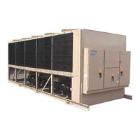
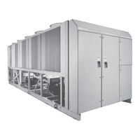
YCAS AIR-COOLED LIQUID CHILLERS STYLE G
Brand:
York
| Category:
Chiller
| Size: 6.17 MB
Table of Contents
Safety Symbols
3
Table of Contents
4
Section 1 - General Chiller
9
Warranty
9
About this Manual
10
Misuse of Equipment
10
Suitability for Application
10
Structural Support
10
Mechanical Strength
10
General Access
10
Pressure Systems
10
Electrical
10
Rotating Parts
11
Sharp Edges
11
Refrigerants and Oils
11
High Temperature and Pressure Cleaning
11
Emergency Shutdown
11
Responsibility for Safety
10
Fig. 1 - Component Locations
12
Evaporator
13
Condenser
13
Introduction
12
General Description
12
Compressor
12
Introduction
9
Safety
9
Standards for Safety
9
Section 2 - Product Description
12
Fig. 2 - Screw Compressor
13
Economizer
14
Oil Separator/System
14
Oil Cooling
14
Capacity Control
14
Power and Control Panel
14
Each Power Compartment Contains
15
The Control Section Contains
15
The Options Sections Contain
15
Microprocessor Controls
15
Motor Current Protection
15
Motor Protection Modules (2ACE)
16
Current Overload
16
Thermal Overload
17
Current Imbalance (Loaded & Unloaded)
17
Loss of Phase
17
Improper Phase Sequence
17
TABLE 1 - Motor Protector Dip Switch Setting
18
Keypad Controls
22
Display
22
Program
23
Motor Starting
22
Accessories and Options
23
Multiple Point Power Connection (Standard)
23
Single-Point Power Connection with Individual Circuit Protection
23
Single-Point Power Connection with Combined Circuit Protection
23
Single-Point Power Connection Without Circuit Protection
23
Control Circuit Terminal Block
23
Building Automation System (BAS) Interface
23
Condenser Coil Protection
23
DX Evaporator and Starter Options
24
Fan Options
24
Sound Reduction Options
24
Unit Enclosures Options
24
Vibration Isolation
24
Nameplate Engineering Data
25
Unit Nomenclature
25
Product Identification Number (Pin)
26
Delivery and Storage
27
Inspection
27
Moving the Chiller
27
Lifting Weights
27
Section 3 - Handling and Storage
27
Fig. 3 - Unit Rigging
28
Fig. 4 - Lifting Lugs
28
Unit Rigging
28
Indoor Installations
29
Location Clearances
29
Location Requirements
29
Outdoor Installations
29
Section 4 - Installation
29
Compressor Feet Bolt Removal
30
Fig. 5 - Compressor Mounting
30
Pipework Connection
31
General Requirements
31
Shipping Braces
31
Vibration Isolators
31
Installation
31
Water Treatment
32
Connection Types & Sizes
33
Ductwork Connection
33
General Requirements
33
Evaporator Connections
33
Optional Flanges
33
Fig. 7 - Victaulic Groove
33
Fig. 8 - Flange Attachments
33
Pipework Arrangement
33
Refrigerant Relief Valve Piping
33
115Vac Control Supply Transformer
34
Remote Emergency Stop Device
35
Electrical Connection
34
Power Wiring
34
Standard Units with Multi Point Power Supply Wiring
34
Units with Single-Point Power Supply Wiring
34
Control Panel Wiring
35
System Inputs
35
Flow Switch
35
Remote Run / Stop
35
Remote Print
35
Volts Free Contacts
35
Chilled Liquid Pump Starter
35
Run Contact
35
Alarm Contacts
35
Fig. 9 - Power Panel Section
36
Fig. 10 - Option Panel Section
37
Fig. 11 - Logic Section Layout
38
Fig. 12 - Logic Section Layout with
39
Fig. 13 - Customer Connections
40
Fig. 14 - Customer Connections
41
Preparation
42
Preparation - Power off
42
Inspection
42
Refrigerant Charge
42
Valves
42
Compressor Oil
42
Fans
42
Isolation/Protection
42
Control Panel
42
Switch Settings
43
Crankcase Heaters
43
Water System
43
Flow Switch
43
Temperature Sensor(S)
43
Control Supply
43
Programmed Options
43
Programmed Settings
43
Date and Time
43
Start/Stop Schedule
43
Section 5 - Commissioning
42
First Time Start-Up
44
Interlocks
44
System Switches
44
Start-Up
44
Oil Pressure
44
Refrigerant Flow
44
Fan Rotation
44
Suction Superheat
44
Expansion Valve
44
General Description
46
Normal Running and Cycling
46
Section 6 - Operation
46
Shutdown
46
Start-Up
46
Fig. 15 - Flow Rate and Pressure Drop Charts
48
Fig. 16 - Glycol Correction Factors
48
Flow Rate and Pressure Drop Charts
48
Glycol Correction Factors
48
Section 7 - Technical Data
48
Temperature and Flows
49
Physical Data
51
Operating Limitations and Sound Power Data
53
Electrical Data
54
Electrical Notes
62
Fig. 17 - Wiring Diagram - Across-The-Line Start
64
Wiring Diagram
64
Fig. 18 - Wiring Diagram - Across-The-Line Start
65
Elementary Diagram
66
Fig. 19 - Elementary Diagram - Across-The-Line Start
66
Fig. 20 - Wiring Diagram - Wye-Delta Start
68
Fig. 21 - Elementary Diagram - Wye-Delta Start
69
Fig. 22 - Elementary Diagram - Wye-Delta Start
70
Fig. 22A - Power Panel (System #1)
72
Fig. 22B - Control Panel Component
73
Fig. 22C - Power Panel (System #2)
74
Connection Diagram (System Wiring)
77
Compressor Terminal Box
78
Dimensions-Ycas0130-Ycas0180 (English)
82
Fig. 23 - Model Ycas0130 - 0180 Dimensions (English)
82
Dimensions-Ycas0130-Ycas0180 (Si)
84
Dimensions-Ycas0200-Ycas0230 (English)
86
Fig. 25 - Model Ycas0200 - Ycas0230 Dimensions (English)
86
Dimensions-Ycas0200-Ycas0230 (Si)
88
Fig. 26 - Model Ycas0200 - Ycas0230 Dimensions (Si)
88
Fig. 27 - Clearances
90
Technical Data
90
Weight Distribution and Isolator Mounting Positions
91
Fig. 28 - Cp-2-XX
92
Isolator Details
92
Fig. 29 - Isolator Details
93
Fig. 30 - Cp-2-XX
96
Fig. 31 - Isolator Details
97
Fig. 32 - Cp-2-XX
100
Fig. 33 - Isolator Details
101
Fig. 34 - Cp-2-XX
104
Fig. 35 - Isolator Details
105
Installation Instructions for VMC Series Awr/Awmr and Cp Restrained Mountings
107
Fig. 36 - Refrigerant Flow Diagram
108
Fig. 37 - Process and Instrumentation Diagram
109
Component Locations
110
Control Panel
110
Fig. 38 - Component Locations
110
Compressor Components
111
Fig. 39 - Compressor Components
111
Fig. 40 - Compressor Components
112
Fig. 41 - Compressor Components
113
Fig. 42 - Compressor Components
114
Fig. 43 - Compressor Components
115
Fig. 44 - Compressor Components
116
System Startup Checklist
117
Unit Checks (no Power)
117
Panel Checks
118
Programmed Values
118
Checking Subcooling and Superheat
119
Initial Start-Up
119
Checking Economizer Superheat
120
Leak Checking
120
Display and Status Information Keys
122
On / off Rocker Switch
122
Program & Setup Keys
122
Programming and Data Access Keys
122
1 Introduction & Physical Description
123
1.1 General
123
1.2 Keypad & Display
123
1.3 Unit (Chiller) on / off Switch
124
1.4 Microprocessor Board
124
1.5 Ancillary Circuit Boards
124
1.6 Circuit Breakers
125
1.8 Transformers
125
1.9 Motor Protection Modules
125
Fig. 45 - Motor Protection Module
127
EMS/BAS Controls
128
Microprocessor Board Layout
130
Fig. 46 - Component Layout
130
Logic Section Layout
131
Fig. 47 - Logic Section Layout
131
Anti-Recycle Timer
132
Anti-Coincidence Timer
132
Evaporator Pump Control
132
Compressor Heater Control
132
Evaporator Heater Control
132
Pumpdown (EEV) Control
132
Alarms
133
Run Status (Chiller)
133
Lead / Lag Compressor Selection
133
Economizer Solenoid Control
134
Fig. 47A - Process and Instrumentation
135
Diagram
135
2 Status Key: General Status Messages & Fault Warnings
136
General
136
General Status Messages
136
Unit Warnings
137
Anticipation Control Status
138
Unit Fault Status Messages
139
System Fault (SAFETY) Status
140
Fig. 48 - Suction Pressure Cutout
141
Printout on Fault Shutdown
143
3 Display Keys & Option Switches
144
General
144
Chilled Liquid Temps Key
144
System # Data Keys
145
Ambient Temp Key
145
Motor Current Key
146
Operating Hrs / Start Counter Key
146
Options Key
146
Fig. 49 - Enlarged Photograph of Dip Switches on Microprocessor Board
147
Funtion Key
148
4 Print Keys
149
General
149
Oper Data Key
149
Operating Data - Software Version
149
Operating Data - Remote Printout
151
History Key
152
Fault History Data - Local Display Messages
152
Fault History Data - Remote Printout
156
5 Entry Keys
157
General
157
Numerical Keypad
157
Enter Key
157
Cancel Key
157
Keys
157
6 Setpoints Keys & Chilled Liquid Control
158
General
158
Chilled Liquid Temperature Control
158
Local Cooling Setpoints Key
162
Remote Cooling Setpoints Key
162
7 Clock Keys
163
General
163
Set Time Key
163
Set Schedule / Holiday Key
164
7.4 Manual Override Key
165
8 Program Key
166
General
166
Program Key - User Programmable Value
166
Programming "Default" Values
170
8.4 Electronic Expansion Valve
172
Fig. 50 - Electronic Expansion Valve
172
8.5 Eev Operation
173
8.6 Eev Programming
175
TABLE 2 - Programmable Values Table
175
(Minimum/Maximum)
175
8.7 Eev Troubleshooting
176
8.8 Condenser Fan Control
177
Fig. 51 - Condenser Fan Layout for
177
Dxst 2 Compressor Units
177
Data for DXST Units with 4 Fans/System
178
Data for DXST Units with 5 Fans/System
178
TABLE 3 - Condenser Fan Control and Fan Contactor
178
TABLE 4 - Condenser Fan Control and Fan Contactor
178
8.9 Service Mode: Unit Setup
179
TABLE 5 - Service Mode Programmable Values
179
TABLE 6 - YCAS Style G, Across the Line Start
180
TABLE 7 - YCAS Style G, Wye Delta Start
182
8.10 Sensor Calibration Charts
185
8.11 Control Inputs/Outputs
186
TABLE 8 - Digital Outputs
186
TABLE 9 - Analog Inputs
187
TABLE 10 - Digital Inputs
188
TABLE 11 - Analog Outputs
188
8.12 Isn Control
189
TABLE 12 - ISN Received Data
189
TABLE 13 - ISN Transmitted Data
189
TABLE 14 - ISN Operational and Fault Codes
192
Section 9 - Maintenance
194
General Requirements
194
Condenser Coils
194
Chiller / Compressor Operating Log
195
Scheduled Maintenance
195
On-Board Battery Back-Up
195
Overall Unit Inspection
195
Compressor Unit Operation
196
General Periodic Maintenance Checks
198
Standard Units
198
Recommended Spares
199
Recommended Compressor Oils
199
Troubleshooting Guide
200
Limited Warranty York Americas Engineered Systems
202
Warranty on New Equipment
202
Warranty on Reconditioned or Replacement Materials
202
Temperature Conversion Chart
203
Actual Temperatures
203
Temperature Conversion Chart Differential Temperatures
203
Pressure Conversion Charrt - Gauge or Differential
203
York YCAS0210 Installation Operation & Maintenance (168 pages)
AIR-COOLED SCREW LIQUID CHILLERS
Brand:
York
| Category:
Chiller
| Size: 6.08 MB
Table of Contents
Table of Contents
2
General Chiller Information & Safety
6
Introduction
6
Warranty
6
Safety
6
Standards for Safety
6
Responsibility for Safety
7
About this Manual
7
Misuse of Equipment
7
Suitability for Application
7
Structural Support
7
Mechanical Strength
7
General Access
7
Pressure Systems
7
Electrical
7
Rotating Parts
8
Sharp Edges
8
Refrigerants and Oils
8
High Temperature and Pressure Cleaning
8
Emergency Shutdown
8
Section 2 Product Description
9
Introduction
9
General Description
9
Compressor
9
Evaporator
10
Condenser
10
Economizer
11
Suction Line Heat Exchanger
11
Oil Separator / System
11
Oil Cooling
12
Capacity Control
12
Power and Control Panel
12
Microprocessor Controls
12
Motor Current Protection
13
Motor Protection Module
13
Current Overload
14
Thermal Overload
14
Current Imbalance / Loss of Phase
14
Improper Phase Sequence
14
Motor Protector Dip Switch Settings
15
Motor Starting
19
Keypad Controls
19
Display
19
Entry
20
Setpoints
20
Clock
20
Print
20
Program
20
Accessories and Options
20
Multiple Point Power Connection (Standard)
20
Single-Point Power Connection with Individual Circuit Protection
20
Single-Point Power Connection with Combined Circuit Protection
20
Single-Point Power Connection Without Circuit Protection
20
DX Cooler Options
21
300 PSIG (21 Bar) Waterside Design Working
21
Pressure
21
1-1/2" (38 MM) Insulation
21
Flange Accessory
21
Remote DX Cooler
21
Flow Switch Accessory
21
Star-Delta Compressor Motor Starter
21
Unit Enclosures
21
Fans
21
Unit Nomenclature and Nameplate Engineering Data
22
Basic Part Number
22
Options Section of Part Number
22
Section 3 Handling and Storage
23
Delivery and Storage
23
Inspection
23
Moving the Chiller
23
Lifting Weights
23
Unit Rigging
24
Section 4 Installation
25
Location Requirements
25
Outdoor Installations
25
Indoor Installations
25
Location Clearances
25
Installation of Vibration Isolators
26
Installation
26
Shipping Braces
26
Pipework Connection
26
General Requirements
26
Water Treatment
27
Pipework Arrangement
28
Connection Types & Sizes
28
Cooler Connections
28
Option Flanges
28
Refrigerant Relief Valve Piping
28
Ductwork Connection
28
General Requirements
28
Electrical Connection
29
Power Wiring
29
Standard Units with Multi Point Power Supply Wiring
29
Units with Single-Point Power Supply Wiring
29
115VAC Control Supply Transformer
29
Remote Emergency Stop Device
30
Control Panel Wiring
30
Volts Free Contacts
30
Chilled Liquid Pump Starter
30
Run Contact
30
Alarm Contacts
30
System Inputs
30
Flow Switch
30
Remote Run/Stop
30
Remote Print
30
Power and Control Panel Layouts (Wye-Delta Typical)
31
Options Panel Layout (Typical)
32
Logic Section Layout
33
Logic Section Layout with Control Panel Layout
34
Customer Connections
35
Section 5 Commissioning
37
Preparation
37
Preparation - Power off
37
First Time Start-Up
39
Section 6 Operation
40
General Description
40
Start-Up
40
Normal Running and Cycling
40
Shutdown
40
Section 7 Technical Data
41
Flow Rate and Pressure Drop Charts
41
Glycol Correction Factors
41
Temperature and Flows
42
Physical Data (English & si Units)
43
Operating Limitations & Sound Power Data
44
Electrical Data
46
Multiple Point Power Supply Connection
46
Optional Single-Point Power Supply Connection and Individual System Circuit Breakers
48
Optional Single-Point Power Supply Connection with Field Supplied Circuit Protection
50
Optional Single-Point Power Supply Connection to Factory Circuit Breaker
51
Compressor Data
52
Fan Data
52
Electrical Notes
53
Wiring Diagram Across-The-Line Start
54
Elementary Diagram - Across-The-Line Start
56
Panel Component Locations
58
Wiring Diagram Wye-Delta Start
60
Elementary Diagram - Wye-Delta Start
62
Panel Component Locations
64
Connection Diagram
68
Compressor Terminal Box
69
Dimensions
72
YCAS0130 - 0180 (English)
72
Ycas0130 - 0180 (Si)
74
YCAS0200 - 0230 (English)
76
Ycas0200 - 0230 (Si)
78
Clearances
80
Weight Distribution and Isolator Mounting Positions
81
Isolator Installation Instructions for VMC Series AWR/AWMR Isolator and CP Restrained Mountings
89
Refrigerant Flow Diagram
90
Process and Instrumentation Diagram
91
Component Locations
92
Compressor Components
93
System Startup Checklist
99
Unit Checks
99
Panel Checks
100
Initial Start-Up
101
Checking Subcooling and Superheat
101
Checking Economizer Superheat
102
Leak Checking
102
Chiller Control Panel Programming and Data Access Keys
103
Display and Status Information Keys
103
ON / off Rocker Switch
103
Program & Setup Keys
103
Section 8 Micro Panel Contents
104
Introduction & Physical Description
104
1.1 General
104
1.2 Keypad & Display
104
1.3 Unit (Chiller) on / off Switch
105
Microprocessor Board
105
1.5 Ancillary Circuit Boards
105
1.6 Circuit Breakers
106
Current Transformers (C.T.)
106
Transformers
106
Motor Protection Modules
107
Ems/Bas Controls
109
Microprocessor Board Layout
111
Logic Section Layout
112
Anti-Recycle Timer
113
Anti-Coincidence Timer
113
Evaporator Pump Control
113
Compressor Heater Control
113
Evaporator Heater Control
113
Pumpdown (LLSV) Control
113
Alarms
113
Run Status (Chiller)
114
Lead / Lag Compressor Selection
114
Status Key: General Status Messages and Fault Warnings
115
General
115
General Status Messages
115
Unit Warnings
116
Anticipation Control Status Messages
117
Unit Fault Status Messages
118
System Fault (Safety) Status Messages
119
Printout on Fault Shutdown
122
Display Keys & Option Switches
123
General
123
Chilled Liquid Temps Key
123
System # Data Keys
124
Ambient Temp Key
124
Motor Current Key
125
Operating HRS / Start Counter Key
125
Options Key & Dip Switch Settings
125
Function Key
127
Print Keys
128
General
128
Oper Data Key
128
Operating Data - Local Display Messages
128
Operating Data - Remote Printout
129
History Key
131
Fault History Data - Local Display Messages
131
Fault History Data - Remote Printout
134
Entry Keys
135
General
135
Numerical Keypad
135
Enter Key
135
Cancel Key
135
Áâ KEYS
135
Setpoints Keys & Chilled Liquid Control
136
General
136
Chilled Liquid Temperature Control
136
Local Cooling Setpoints Key
139
Remote Cooling Setpoints Key
139
Clock Keys
140
General
140
Set Time Key
140
Set Schedule / Holiday Key
141
Manual Override Key
142
Program Key
143
General
143
Program Key - User Programmable Values
143
Programming "Default" Values
147
Condenser Fan Control
148
Section 9 Maintenance
155
General Requirements
155
Daily Maintenance
155
Scheduled Maintenance
155
Chiller / Compressor Operating Log
155
Compressor Unit Operation
156
Maintenance Requirements
157
General Periodic Maintenance Checks Standard Units
158
Section 10 Spare Parts
159
Recommended Spares
159
Recommended Compressor Oils
159
Associated Drawings
159
Section 11 Troubleshooting
160
Competent Persons Troubleshooting Guide
160
Sensor Calibration Charts
162
Limited Warranty Applied Systems
163
Temperature Conversion Chart
164
YORK Service Offices
165
Related Products
York Millennium YCAS0210EC
York eco YCAS0218EB
York YCAS0218
York MILLENNIUM YCAS0230
York YCAS0200
York Millennium YCAS0250EC
York Millennium YCAS0270EC
York YCAS0248EB
York eco YCAS0268EB
York YCAS0250
York Categories
Air Conditioner
Heat Pump
Chiller
Furnace
Air Handlers
More York Manuals