beautypg.com
Manuals
Brands
York Manuals
Heat Pump
YCUL0035EE
York YCUL0035EE Manuals
Manuals and User Guides for York YCUL0035EE. We have
1
York YCUL0035EE manual available for free PDF download: Installation, Operation And Maintenance Manual
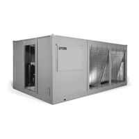
York YCUL0035EE Installation, Operation And Maintenance Manual (178 pages)
Air-Cooled Scroll Compressor Condensing Units Style E
Brand:
York
| Category:
Heat Pump
| Size: 8.57 MB
Table of Contents
Table of Contents
5
Section 1 - General Equipment Information and Safety
11
Compressors
11
Condenser
11
Introduction
11
Refrigerant Circuit
11
Warranty
11
About this Manual
12
Misuse of Equipment
12
Safety and Quality
12
FIGURE 1 - YCUL Air-Cooled Scroll Compressor Condensing Unit
15
Microcomputer Control Center
16
Building Automation System Interface
17
Communications
17
Power Panel
17
Discharge Pressure Transducers and Readout Capability
18
Section 2 - Product Description
15
General System Description
15
Introduction
15
FIGURE 2 - Unit Components Front
20
FIGURE 3 - Control/Power Panel Components Single System Units
21
FIGURE 4 - Control/Power Panel Components Dual System Units
22
Basic Unit
23
FIGURE 5 - Refrigerant Flow Diagram
27
FIGURE 6 - Process and Instrumentation Diagram
28
FIGURE 7 - Unit Rigging
29
Section 3 - Handling and Storage
29
Delivery and Storage
29
Inspection
29
Unit Rigging
29
Section 4 - Installation
31
Handling
31
Installation Checklist
31
Location and Clearances
31
Compressor Mounting
32
Ductwork Connection
32
Pipework Arrangement
32
Recommendations of the Building Services Research Association
32
Spring Isolators (Optional)
32
Wiring
32
FIGURE 8 - Wiring Options for Remotely Start or Stop the Dual System Unit
33
Compressor Heaters
34
High Pressure Cutout
34
Refrigerant Piping
34
Relief Valves
34
TABLE 2 - Refrigerant Piping Charges
35
TABLE 1 - Fitting Equivalent Lengths
35
TABLE 4 - Refrigerant Line Connections
36
TABLE 3 - Miscellaneous Liquid Line Pressure Drops
36
Filter Driers / Sight Glasses / Txvs
37
Oil Traps
37
Refrigerant Charge
37
Refrigerant Piping Reference
37
FIGURE 9 - Single-Point Supply Connection - Terminal Block, Non-Fused Disconnect Switch
38
FIGURE 10 - Discharge Air Sensor Field Wiring
38
FIGURE 11 - Control Wiring
39
Section 5 - Technical Data
41
Operational Limitations (English)
41
TABLE 5 - Voltage Limitations
41
TABLE 6 - Physical Data (English)
42
TABLE 7 - Physical Data (SI)
43
Electrical Data
44
Physical Data (SI)
43
Physical Data (English)
42
TABLE 9 - Voltage Range
44
TABLE 8 - Micro Panel Power Supply
44
TABLE 10 - Lug Ranges
48
Electrical Notes and Legend
49
FIGURE 12 - Control Wiring Diagram, Single Circuit, IPU II
52
Wiring Diagrams
52
FIGURE 13 - Control Wiring Diagram, Single Circuit, IPU II
55
FIGURE 14 - Control Wiring Diagram, Dual Circuit, IPU II
56
FIGURE 15 - Control Wiring Diagram, Dual Circuit, IPU II
58
FIGURE 16 - Control Wiring Diagram, Details, Single Circuit
60
FIGURE 17 - Control Wiring Diagram, Details, Dual Circuit
62
FIGURE 18 - Power Wiring, Single Circuit
64
FIGURE 19 - Power Wiring, Single Circuit
66
FIGURE 20 - Power Wiring, Single Circuit
68
FIGURE 21 - Power Wiring, Single Circuit
70
FIGURE 22 - Power Wiring, Dual Circuit
72
FIGURE 23 - Power Wiring, Dual Circuit
74
FIGURE 24 - Connection Wiring, Single Circuit
76
FIGURE 25 - Connection Wiring, Single Circuit
78
FIGURE 26 - Connection Wiring, Single Circuit
80
FIGURE 27 - Connection Wiring, Single Circuit
82
FIGURE 28 - Connection Wiring, Dual Circuit
84
FIGURE 29 - Connection Wiring, Dual Circuit
86
FIGURE 30 - Unit Clearances - All Models
92
FIGURE 31 - Sample Isolator Location Drawing
93
FIGURE 32 - Isolator Locations, 60 Hz
94
Isolator Locations (English)
94
FIGURE 33 - Isolator Locations, 50 Hz
95
Isolator Locations (SI)
95
FIGURE 34 - One Inch Deflection Spring Isolator Cross-Reference
96
Isolation Information
96
FIGURE 35 - One Inch Deflection Spring Isolators Installation Instructions
97
One Inch Deflection Spring Isolators Installation Instructions
97
FIGURE 36 - Two Inch Deflection Seismic Isolator Cross-Reference
98
Two Inch Deflection Seismic Isolator Cross-Reference
98
FIGURE 37 - Seismic Isolator Installation and Adjustment
99
Seismic Isolator Installation and Adjustment
99
Durulene Isolator Cross-Reference
100
FIGURE 38 - Durulene Isolator Cross-Reference
100
Installation of Durulene Vibration Isolators
101
Weight Distribution and Isolator Mounting Positions
93
Dimensions (English)
88
Clearances
92
FIGURE 39 - Installation of Durulene Vibration Isolators
101
Section 6 - Commissioning
103
Preparation - Power off
103
Preparation - Power on
104
Equipment Pre-Startup and Startup Checklist
105
Section 7 - Unit Controls
109
Introduction
109
Microprocessor Board
109
Unit Switch
110
Display
110
Keypad
110
Battery Back-Up
110
Transformer
110
Single System Select and Programming # of Compressors
110
TABLE 11 - Status Key Messages Quick Reference List
116
TABLE 12 - Operation Data
120
TABLE 13 - Cooling Setpoints Programmable Limits and Defaults
131
TABLE 14 - Program Key Limits and Defaults
131
TABLE 15 - Setpoints Quick Reference List
132
TABLE 16 - Options Key Programming Quick Reference List
138
Section 8 - Unit Operation
139
Capacity Control
139
Discharge Air Temperature Control
139
Discharge Pressure Limit Controls
139
Suction Pressure Limit Controls
139
FIGURE 40 - Discharge Air Temperature Control
140
TABLE 17 - Discharge Air Temperature Control for 5 and 6 Compressors (7 and 8 Steps)
140
TABLE 18 - Discharge Air Temperature Control for 4 Compressors (6 Steps)
140
FIGURE 41 - Suction Pressure Control
141
Anti-Coincidence Timer
142
Anti-Recycle Timer
142
Compressor Lead/Lag
142
Evaporator Blower Control
142
Evaporator Heater Control
142
Pumpdown Control
142
System Lead/Lag
142
Suction Pressure Control
141
TABLE 20 - YCUL0045 - YCUL0072 Condenser Fan Control Using Discharge Pressure Only
143
FIGURE 42 - YCUL0045 - YCUL0072 Fan Location (Typical)
143
TABLE 22 - YCUL0020 - YCUL0035 Low Ambient Condenser Fan Control - Discharge Pressure Control
144
TABLE 21 - YCUL0020 - YCUL0072 Low Ambient Condenser Fan Control - Discharge Pressure Control
144
TABLE 23 - Compressor Operation - Load Limiting
145
BAS/EMS Discharge Air Temperature Reset Using a Voltage or Current Signal
146
TABLE 19 - YCUL0020 - YCUL0072 Condenser Fan Control Using Outdoor Ambient Temperature and Discharge Pressure
143
Alarm Status
145
Compressor Run Status
145
Load Limiting
145
Section 9 - Service and Troubleshooting
147
Clearing History Buffers
147
Service Mode
147
Service Mode - Outputs
147
Service Mode - Analog and Digital Inputs
148
Service Mode - Condensing Unit Configuration
148
Control Inputs/Outputs
149
TABLE 27 - I/O Analog Outputs
149
TABLE 26 - I/O Analog Inputs
149
TABLE 25 - I/O Digital Outputs
149
TABLE 24 - I/O Digital Inputs
149
FIGURE 43 - Microboard Layout
150
Checking Inputs and Outputs
151
TABLE 28 - Outdoor Air Sensor Temperature/Voltage/Correlation
151
TABLE 29 - Discharge Air Temp. Sensor Temperature/Voltage/Resistance Correlation
152
TABLE 30 - Pressure Transducers
153
FIGURE 44 - I/O Board Relay Contact Architecture
154
FIGURE 45 - Printer to Microboard Electrical Connections
155
TABLE 31 - Troubleshooting
157
Section 10 - Maintenance
159
Important
159
Compressors
159
Condenser Fan Motors
159
Condenser Coils
159
Operating Parameters
159
Onboard Battery Back-Up
159
Overall Unit Inspection
159
Bacnet, Modbus, and Yorktalk 2 Communications
160
TABLE 32 - Minimum, Maximum, and Default Values
161
FIGURE 46 - Micro Panel Connections
161
TABLE 33 - Values Required for Bas Communication
162
TABLE 34 - Real Time Error Numbers
162
TABLE 35 - Bacnet and Modbus Communications Data Map
164
TABLE 36 - Yorktalk 2 Communications Data Map
168
Related Products
York YCUL0030
York YCUL0036
York YCUL0031EE
York YCUL0016
York YCUL0056
York YCUL0080
York YCUL0072EE
York YCUL0045E
York YCUL0081E
York YCUL0095E
York Categories
Air Conditioner
Heat Pump
Chiller
Furnace
Air Handlers
More York Manuals