beautypg.com
Manuals
Brands
York Manuals
Chiller
YK Series
York YK Series Manuals
Manuals and User Guides for York YK Series. We have
3
York YK Series manuals available for free PDF download: Operation Manuals, Operation And Maintenance, Installation Manual
York YK Series Operation Manuals (220 pages)
R-134a COOLING ONLY, WITH OPTIVIEW CONTROL CENTER, FOR ELECTRO-MECHANICAL STARTER, SOLID STATE STARTER AND VARIABLE SPEED DRIVE
Brand:
York
| Category:
Chiller
| Size: 5.96 MB
Table of Contents
Table of Contents
5
Section 1 - Description of System and Fundamentals of Operation
9
System Operation Description
9
FIGURE 1 - Model YK Chiller
9
Capacity Control
10
FIGURE 2 - Compressor Pre-Rotation Vanes
10
FIGURE 3 - Refrigerant Flow-Thru Chiller
11
Section 2 - Optiview Control Center Introduction
13
Optiview Control Center
15
FIGURE 4 - Optiview Control Center
15
TABLE 1 - Addresses and Associated Data
19
Home Screen
21
FIGURE 5 - Home Screen
21
System Screen
25
FIGURE 6 - System Screens
25
Evaporator Screen
27
FIGURE 7 - Evaporator Screen
27
Condenser Screen
31
FIGURE 8 - Condenser Screen
31
Heat Recovery Screen
35
FIGURE 9 - Heat Recovery Screen (Software Version C.opt.01.21.307)
35
Head Pressure Control Screen
39
FIGURE 10 - Head Pressure Control Screen (Software Version C.opt.01.21.307)
39
Heat Pump Screen
41
FIGURE 11 - Heat Pump Screen (Software Version C.OPT.01.23.307 and Later)
41
Refrigerant Level Control Screen
45
FIGURE 12 - Refrigerant Level Control Screen (Flash Memory Card Versions C.mlm.01.06.XXX and Earlier)
45
Refrigerant Level Control Screen
47
FIGURE 13 - Refrigerant Level Control Screen (Software Version C.mlm.01.07.XXX to C.mlm.01.10D.XXX or C.opt.01.10D (and Earlier))
47
Refrigerant Level Control Setpoints Screen
49
FIGURE 14 - Refrigerant Level Control Setpoints Screen
49
Refrigerant Level Control Screen
51
FIGURE 15 - Refrigerant Level Control Screen
51
Compressor Screen
53
FIGURE 16 - Compressor Screen (All "P" Compressors and Style F and Later Chillers with G, Q or H5-8 Com- Pressors)
53
Compressor Screen
57
FIGURE 17 - Compressor Screen
57
Proximity Probe Calibration Screen
61
FIGURE 18 - Proximity Probe Calibration Screen
61
Hot Gas Bypass Screen
63
FIGURE 19 - Hot Gas Bypass Screen
63
Surge Protection Screen
65
FIGURE 20 - Surge Protection Screen
65
Variable Geometry Diffuser Screen
69
FIGURE 21 - Variable Geometry Diffuser Screen
69
Variable Geometry Diffuser Setpoints Screen
71
FIGURE 22 - Variable Geometry Diffuser Setpoints Screen
71
Pre-Rotation Vanes Calibration Screen
75
FIGURE 23 - Pre-Rotation Vanes Calibration Screen
75
VSD Tuning Screen
77
FIGURE 24 - VSD Tuning Screen
77
Oil Sump Screen
79
FIGURE 25 - Oil Sump Screen
79
Electro-Mechanical Starter Screen
83
FIGURE 26 - Electro-Mechanical Starter Screen
83
Mod "A" Solid State Starter Screen
85
FIGURE 27 - Mod "A" Solid State Starter Screen
85
Mod "B" Solid State Starter Screen
87
FIGURE 28 - Mod "B" Solid State Starter Screen
87
Medium Voltage Solid State Starter Screen
89
FIGURE 29 - Medium Voltage Solid State Starter Screen
89
Variable Speed Drive Screen
91
FIGURE 30 - Variable Speed Drive Screen
91
Medium Voltage Variable Speed Drive Screen
93
FIGURE 31 - Medium Voltage Variable Speed Drive Screen (Software Version C.opt.01.16.XXX and Later)
93
TABLE 2 - Voltage (V)
94
Variable Speed Drive (VSD) Details Screen
97
FIGURE 32 - Variable Speed Drive (VSD) Details Screen (Style D VSD and VSD with Part Number 371-03789-XXX (503 Hp 60Hz; 410Hp 50Hz))
97
Variable Speed Drive (VSD) Details Screen
99
Figure 33 - Variable Speed Drive (Vsd) Details Screen (Vsd with Part Number 371-02767-XXX
99
Adaptive Capacity Control Details Screen
101
FIGURE 34 - Adaptive Capacity Control Details Screen (Software Version C.opt.01.18.307 and Earlier) (VSD and MV VSD)
101
Adaptive Capacity Control Details Screen
103
FIGURE 35 - Adaptive Capacity Control Details Screen York Protocol Configuration (Software Version C.opt.01.19.307 and Later)
103
Adaptive Capacity Control Details Screen
105
FIGURE 36 - Adaptive Capacity Control Details Screen Modbus Protocol Configuration (Software Version C.opt.01.19.307 and Later)
105
Surge Map Screen - Table View
109
FIGURE 37 - Surge Map Screen - Table View (Software Version C.opt.01.19.307 and Later)
109
Surge Map Screen - List View
111
FIGURE 38 - Surge Map Screen - List View (Software Version C.opt.01.19.307 and Later)
111
Harmonic Filter Details Screen
113
FIGURE 39 - Harmonic Filter Details Screen (Style D VSD and VSD with Part Number 371-03789-XXX (503Hp 60Hz; 419Hp 50Hz)
113
Motor Lubrication Screen
115
FIGURE 40 - Motor Lubrication Screen
115
Motor Details Screen
119
FIGURE 41 - Motor Details Screen (Software Version C.opt.01.22.307 and Later)
119
Motor Setpoints Screen
123
FIGURE 42 - Motor Setpoints Screen (Software Version C.opt.01.22.307 and Later)
123
Setpoints Screen
127
FIGURE 43 - Setpoints Screen
127
Setup Screen
131
FIGURE 44 - Setup Screen
131
TABLE 3 - Condenser Temperature Range
134
Quick Start Screen
137
FIGURE 45 - Quick Start Screen (Software Version C.opt.01.21.307 and Later)
137
Schedule Screen
141
FIGURE 46 - Schedule Screen
141
User Screen
143
FIGURE 47 - User Screen
143
COMMS Screen
145
FIGURE 48 - COMMS Screen
145
Printer Screen
147
FIGURE 49 - Printer Screen
147
Sales Order Screen
149
FIGURE 50 - Sales Order Screen
149
Operations Screen
151
FIGURE 51 - Operations Screen
151
History Screen
153
FIGURE 52 - History Screen
153
History Details Screen
155
FIGURE 53 - History Details Screen
155
Security Log Screen
157
FIGURE 54 - Security Log Screen
157
Security Log Details Screen
159
FIGURE 55 - Security Log Details Screen
159
Custom View Screen
161
FIGURE 56 - Custom View Screen
161
Custom View Setup Screen
163
FIGURE 57 - Custom View Setup Screen
163
Trend Screen
165
FIGURE 58 - Trend Screen
165
Trend Setup Screen
167
FIGURE 59 - Trend Setup Screen
167
Advanced Trend Setup Screen
169
FIGURE 60 - Advanced Trend Setup Screen
169
Common Slots Screen
171
FIGURE 61 - Common Slots Screen
171
TABLE 4 - Master Slot Numbers List for Use with Trend Feature
172
Section 3 - Display Messages
175
Status Messages
175
Run Messages
176
Start Inhibit Messages
177
Warning Messages
177
Routine Shutdown Messages
181
Cycling Shutdown Messages
181
Mod "B" Solid State Starter Cycling Shutdown Messages
184
Compressor Motor Variable Speed Drive: Cycling Shutdown Messages
186
Safety Shutdown Messages
191
Mod "B" Solid State Starter Safety Shutdown Messages
198
Compressor Motor Variable Speed Drive: Safety Shutdown Messages
199
Section 4 - Printing
203
Printing Overview
203
FIGURE 62 - Printer
203
Acceptable Printers
204
Printer Connections
204
Table 5 - Okidata Okipos 441
204
Printer Setup
205
Control Center Setup
205
Downloading System Prints to Alaptop
205
FIGURE 63 - Breckman Printer
207
FIGURE 64 - Communications Block Diagram
207
TABLE 6 - Brecknell CP130
207
FIGURE 65 - Sample Printout (Status)
208
FIGURE 66 - Sample Printout (Setpoints)
210
FIGURE 67 - Sample Printout (Schedule)
212
FIGURE 68 - Sample Printout (Sales Order)
212
FIGURE 69 - Sample Printout (History)
214
FIGURE 70 - Sample Printout (Security Log Report)
216
FIGURE 71 - Sample Printout (Trend Data New or Existing Points)
216
FIGURE 72 - Sample Printout (Custom Screen Report)
216
FIGURE 73 - Sample Printout (Adaptive Capacity Control New Map Point Report)
217
FIGURE 74 - Sample Printout (Adaptive Capacity Control Existing Map Points Report)
217
TABLE 7 - si Metric Conversion
219
York YK Series Operation And Maintenance (38 pages)
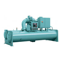
CENTRIFUGAL LIQUID CHILLERS
Brand:
York
| Category:
Chiller
| Size: 1.72 MB
Table of Contents
Table of Contents
5
Section 1 - Description of System and Fundamentals of Operation
7
System Operation Description
7
Capacity Control
7
FIGURE 1 - Compressor Prerotation Vanes
7
FIGURE 2 - Refrigerant Flow-Thru Chiller (Falling Film Evaporator)
8
Section 2 - System Operating Procedures
9
Checking the Oil Level in the Oil Reservoir
9
FIGURE 3 - Oil Level Indicator
9
Oil Heater Operation
9
Oil Heaters
9
Start-Up
9
Start-Up Procedure
9
FIGURE 5 - Chiller Starting Sequence and Shutdown Sequence (Variable Speed Drive)
10
FIGURE 4 - Chiller Starting Sequence and Shutdown Sequence (Em Starter and Solid State Starter)
10
FIGURE 6 - Liquid Chiller Log Sheets
12
Need for Maintenance or Service
13
Prolonged Shutdown
13
Stopping the System
13
Chiller Operation
11
Condenser Water Temperature Control
11
Operating Log Sheet
11
Operating Inspections
12
Section 3 - System Components Description
15
Capacity Control
15
Compressor
15
Compressor Lubrication System
15
General
15
Oil Pump
15
FIGURE 7 - System Components Front View
16
FIGURE 8 - System Components Rear View
17
FIGURE 9 - Schematic Drawing - (Yk) Compressor Lubrication System
18
FIGURE 10 - Oil Return System
21
Oil Charging Procedure
22
The Oil Charge
22
Heat Exchangers
19
Motor Driveline
19
Oil Heater
19
Refrigerant Flow Control
19
Optional Hot Gas Bypass
20
Optional Service Isolation Valves
20
Optiview Control Center
20
Solid State Starter (Optional)
20
Variable Speed Drive (Optional)
20
Section 4 - Operational Maintenance
21
Oil Return System
21
Changing the Dehydrator
21
FIGURE 11 - Charging Oil Reservoir with Oil
22
TABLE 1 - Operation Analysis Chart
23
Section 5 - Troubleshooting
23
FIGURE 12 - Evacuation of Chiller
25
Vacuum Testing
26
Section 6 - Maintenance
25
Checking System for Leaks
25
Conducting R-134A Pressure Test
25
Renewal Parts
25
TABLE 2 - System Pressures
26
FIGURE 13 - Saturation Curve
27
Checking the Refrigerant Charge During Unit Shutdown
28
Handling Refrigerant for Dismantling and Repairs
28
Megging the Motor
28
Operation
27
Refrigerant Charging
27
Vacuum Dehydration
27
FIGURE 14 - Diagram, Megging Motor Windings
28
FIGURE 15 - Motor Starter Temperature and Insulation Resistances
29
Compressor
32
Electrical Controls
32
Section 7 - Preventive Maintenance
33
Compressor
33
Compressor Motor
33
Greased Bearings
33
Motor Re-Lubrication Instruction
33
Leak Testing
34
Evaporator and Condenser
34
Oil Return System
35
Electrical Controls
35
Temperature
37
TABLE 3 - si Metric Conversion
37
York YK Series Installation Manual (34 pages)
Chillers (Style H) Field Reassembly for Form 3, 7, 9, and 10 Shipment
Brand:
York
| Category:
Chiller
| Size: 4.8 MB
Table of Contents
Table of Contents
3
General Safety Guidelines
5
Safety Symbols
5
Changeability of this Document
6
Associated Literature
6
Nomenclature
7
Shipping and Reassembly
8
Forms of Shipment
8
Form 3 - Driveline Separate from Shells
8
Form 7 - Split Shells
9
Form 9 - Unit Separate from Variable Speed Drive
9
Form 10 - Unit Separate from Variable Speed Drive
9
Inspection - Damage - Shortage
10
Data Plates
10
Long-Term Storage
11
Shipment Form 2/3/7/9
13
Shipment Form 1/10
13
Reassembly
13
Form 7 Shipment
13
Form 3 and Form 7 Shipment
14
Form 9 and Form 10 Reassembly
15
Q3-Q8 Compressors (with Falling Film)
17
Q3-Q8 Compressors
19
P8-P9, H9 Compressors (with Falling Film)
20
P8-P9 and H9 Compressors
22
K Compressors
23
Weights
26
Unit Conversion
34
Related Products
York Millennium YK M3 M3 G4 THRU YK S6 S4 J2
York Millennium YK S6 S4 J2
York YK Style H
York YK
York CodePak YK L1 L1 G4
York CodePak YK S2 S2 J4
York YK-EP B
York YK-EP
York Latitude YCIV0227V
York YCH120
York Categories
Air Conditioner
Heat Pump
Chiller
Furnace
Air Handlers
More York Manuals