beautypg.com
Manuals
Brands
York Manuals
Chiller
YLAA0170
York YLAA0170 Manuals
Manuals and User Guides for York YLAA0170. We have
2
York YLAA0170 manuals available for free PDF download: Manual, Installation Operation & Maintenance
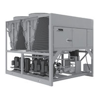
York YLAA0170 Manual (206 pages)
Air-Cooled Scroll Chiller
Brand:
York
| Category:
Chiller
| Size: 15.56 MB
Table of Contents
Table of Contents
5
Section 1 - General Chiller Information and Safety
11
Introduction
11
Warranty
11
Handling
11
Safety and Quality
11
About this Manual
12
Misuse of Equipment
12
Section 2 - Product Description
15
Introduction
15
General System Description
15
FIGURE 1 - Compressor Enclosure for YLAA0041HE
16
TABLE 1 - Canadian Registration Numbers
16
Communications
18
Building Automation System Interface
18
Power Panel
18
Accessories and Options
18
FIGURE 2 - Unit Components (Front)
21
FIGURE 3 - Unit Components (Side)
22
FIGURE 4 - Power Panel Components
23
FIGURE 5 - Power Panel / Control Components
24
TABLE 2 - Complete Pin Number Description
25
FIGURE 6 - Process and Instrumentation Diagram
31
Section 3 - Handling and Storage
33
FIGURE 7 - Rigging and Lifting Label
33
Delivery and Storage
34
Inspection
34
Moving the Chiller
34
FIGURE 8 - Unit Rigging/Lifting
35
Lifting Weights
36
Lifting Using Lugs
36
Lifting Using Shackles
36
FIGURE 9 - Lifting Lugs
36
Section 4 - Installation
37
Installation Checklist
37
Startup/Commissioning
37
Location and Clearances
37
Spring Isolators (Optional)
38
Compressor Mounting
38
Chilled Liquid Piping
38
Pipework Arrangement
39
Wiring
39
FIGURE 10 - Chilled Liquid System
39
Relief Valves
40
High Pressure Cutout
40
Single-Point Supply Connection - Terminal Block, Non-Fused
41
Disconnect Switch or Circuit Breaker
41
FIGURE 11 - Single-Point Supply Connection - Terminal Block, Non-Fused Disconnect Switch
41
FIGURE 12 - Control Wiring Inputs
42
TABLE 3 - Chemical Specification of Water
43
FIGURE 13 - Thermal Dispersion Flow Switch
44
FIGURE 14 - Wiring of Thermal Dispersion Flow Switch
44
FIGURE 15 - Control Wiring Outputs
46
Section 5 - Technical Data
47
TABLE 4 - Temperatures and Flows
47
TABLE 5 - Ethylene and Propylene Glycol Correction Factors
49
Physical Data YLAA0041 - YLAA0230 60 Hz
50
TABLE 6 - Physical Data (English) 60 Hz
50
Electrical Data
54
Compressor Heaters
54
TABLE 7 - Micropanel Power Supply
54
TABLE 8 - Voltage Range
54
TABLE 9 - Pump Electrical Data 60 Hz
55
TABLE 10 - Transformer Load
55
TABLE 11 - Electrical Data Without Pumps
56
TABLE 12 - Wiring Lugs
62
Electrical Notes
65
FIGURE 16 - Elementary Wiring Diagram
71
FIGURE 17 - Elementary Wiring Diagram
72
FIGURE 18 - Fan Wiring, Standard Air Flow
74
FIGURE 19 - Fan Wiring, High Air Flow
76
FIGURE 20 - Single and Dual Point Wiring Options
78
FIGURE 21 - Pump Wiring
80
FIGURE 22 - EEV Controller Elementary Diagram
82
FIGURE 23 - Compressor Wiring
84
FIGURE 24 - Power Options Connection Diagram
87
FIGURE 25 - Power Panel
88
FIGURE 26 - Micro Panel Connections
91
FIGURE 27 - Four Fan Units Dimensions - YLAA0041HE, YLAA0048HE, YLAA0058HE, YLAA0065HE
92
FIGURE 28 - Four Fan Units Dimensions - YLAA0070SE, YLAA0080SE, YLAA0089SE
93
FIGURE 29 - Five Fan Units Dimensions - YLAA0100SE
94
FIGURE 30 - Six Fan Units Dimensions - YLAA0092HE, YLAA0101HE, YLAA0115SE, YLAA0120SE
95
FIGURE 31 - Eight Fan Units Dimensions - YLAA0125HE, YLAA0136SE, YLAA0139HE, YLAA0142HE
96
FIGURE 32 - Ten Fan Units Dimensions - YLAA0170SE, YLAA0156HE, YLAA0175HE
97
FIGURE 33 - Twelve Fan Units Dimensions - YLAA200HE, YLAA0230HE
98
Weight Distribution and Isolator Mounting Positions
99
FIGURE 34 - Sample Printout Supplied in the Isolator Package and in the Chiller Panel Literature Packet
99
Clearances
100
FIGURE 35 - Unit Clearances - All Models
100
Isolator Locations
101
Isolator Information
104
Section 6 - Commissioning
111
Preparation - Power off
111
FIGURE 36 - EEV IB-G Interface Board
113
Commissioning the Pump VFD
114
Preparation - Power on
114
FIGURE 37 - Drive Display
116
TABLE 13 - Drive Programming Parameters
116
FIGURE 38 - Circuit Breaker Panel
117
Determining Proper Oil Levels
118
FIGURE 39 - Tandem Set
118
FIGURE 40 - Trio Set
118
Section 7 - Unit Controls
123
Introduction
123
IPU II and I/O Boards
123
Transformer
124
Display
124
Keypad
124
Unit Switch
124
Battery Backup
124
Programming the Number of Compressors
124
Status Key
125
TABLE 14 - YLAA Fault and Inhibit Codes
131
TABLE 15 - Legend
131
FIGURE 41 - Status Key Messages Quick Reference List
132
Display/Print Keys
133
FIGURE 42 - Operation Data
136
Entry Keys
141
Setpoints Keys
142
Schedule/Advance Day Key
143
TABLE 16 - Cooling Setpoint, Programmable Limits, and Defaults
144
Program Key
145
TABLE 17 - Program Key Limits and Default
147
FIGURE 43 - Setpoints Quick Reference List
148
TABLE 18 - Program Key Limits and Default
149
Unit Keys
151
FIGURE 44 - Unit Keys Options Programming Quick Reference List
158
Bacnet, Modbus, N2, and Yorktalk 2 Communications
159
FIGURE 45 - Micro Panel Connections
160
TABLE 19 - Minimum, Maximum and Default Values
160
TABLE 20 - Values Required for BAS Communication
161
TABLE 21 - Real Time Error Numbers
162
TABLE 22 - Native Bacnet, Modbus and N2 Communications Data Map
163
TABLE 23 - Yorktalk 2 Communications Data Map
168
Section 8 - Unit Operation
175
Capacity Control
175
Suction Pressure Limit Controls
176
Discharge Pressure Limit Controls
176
Leaving Chilled Liquid Control
176
FIGURE 46 - Leaving Water Temperature Control Example
176
Leaving Chilled Liquid Control Override to Reduce Cycling
177
FIGURE 47 - Setpoint Adjust
177
TABLE 24 - Sample Compressor Staging for Return Water Control
177
Leaving Chilled Liquid System Lead/Lag and Compressor Sequencing
178
Return Chilled Liquid System Lead/Lag and Compressor Sequencing
178
Anti-Recycle Timer
178
Anti-Coincidence Timer
178
Evaporator Pump Control and YORK Hydro Kit Pump Control
178
Evaporator Heater Control
179
Pumpdown Control
179
Standard Condenser Fan Control
179
VSD Fan
179
Changing the Switch Point of the Thermal Dispersion Flow Switch
179
FIGURE 48 - Condenser Fan Locations
180
TABLE 25 - YLAA Standard Condenser Fan Control Using Discharge Pressure Only (2, 3, or 4 Fans Per System)
181
TABLE 26 - YLAA Standard Condenser Fan Control Using Discharge Pressure Only
181
Load Limiting
183
Compressor Run Status
183
Alarm Status
183
TABLE 27 - Compressor Operation Load Limiting
183
Remote BAS/EMS Temperature Reset Using a Voltage or Current Signal
184
Section 9 - Service and Troubleshooting
185
Clearing History Buffers
185
Resetting System Lockout Faults
185
Service Mode
185
Service Mode - Outputs
185
Service Mode - Chiller Configuration
186
Service Mode - Analog and Digital Inputs
186
Control Inputs/Outputs
187
TABLE 28 - I/O Digital Inputs
187
TABLE 29 - I/O Digital Outputs
187
TABLE 30 - I/O Analog Inputs
187
TABLE 31 - I/O Analog Outputs
187
FIGURE 49 - Microboard Layout
188
Checking Inputs and Outputs
189
TABLE 32 - Outdoor Air Sensor Temperature/Voltage/Correlation
189
TABLE 33 - Entering/Leaving Chilled Liquid Temp. Sensor, Temperature/Voltage Correlation
190
TABLE 34 - Pressure Transducers
191
FIGURE 50 - I/O Board Relay Contact Architecture
192
TABLE 35 - Data Logging to Flash
193
Optional Printer Installation
195
FIGURE 51 - Printer to Microboard Electrical Connections
196
Troubleshooting
197
TABLE 36 - Troubleshooting
197
Section 10 - Maintenance
199
Compressors
199
Condenser Fan Motors
199
Condenser MCHX Cleaning
199
Operating Parameters
201
On-Board Battery Backup
201
Thermal Dispersion Flow Switch
201
Brazed Plate Heat Exchanger (Evaporator) Heater
201
Overall Unit Inspection
201
TABLE 37 - si Metric Conversion
205
York YLAA0170 Installation Operation & Maintenance (178 pages)
AIR-COOLED SCROLL CHILLERS WITH BRAZED PLATE HEAT EXCHANGER STYLE B (60 HZ) 4-10 FAN, 55 - 230 TON, 195 - 700 KW
Brand:
York
| Category:
Chiller
| Size: 12.02 MB
Table of Contents
Table of Contents
5
Section 1 - General Chiller Information and Safety
11
Introduction
11
Warranty
11
Handling
11
Safety and Quality
11
About this Manual
12
Misuse of Equipment
12
Section 2 - Product Description
15
General System Description
15
Introduction
15
TABLE 1 - Canadian Registration Numbers
16
Building Automation System Interface
17
Communications
17
Power Panel
17
Accessories and Options
18
FIGURE 1 - Unit Components (Front)
20
FIGURE 2 - Unit Components (Side)
21
FIGURE 3 - Power Panel Components
22
FIGURE 4 - Power Panel / Control Components
23
TABLE 2 - Complete Pin Number Description
24
FIGURE 5 - Process and Instrumentation Diagram
29
Section 3 - Handling and Storage
31
Delivery and Storage
31
Inspection
31
Moving the Chiller
31
FIGURE 6 - Unit Rigging/Lifting
32
Lifting Using Lugs
33
Lifting Using Shackles
33
Lifting Weights
34
FIGURE 7 - Warning
34
Section 4 - Installation
35
Installation Checklist
35
Location and Clearances
35
Startup/Commissioning
35
Chilled Liquid Piping
36
Compressor Mounting
36
Remote Cooler Option
36
Spring Isolators (Optional)
36
FIGURE 8 - Chilled Liquid System
37
Pipework Arrangement
37
Wiring
37
High Pressure Cutout
38
Relief Valves
38
Single-Point Supply Connection - Terminal Block, Non-Fused Disconnect Switch or Circuit Breaker
39
FIGURE 9 - Single-Point Supply Connection - Terminal Block, Non-Fused Disconnect Switch or
39
FIGURE 10 - Control Wiring Inputs
40
FIGURE 11 - Thermal Dispersion Flow Switch
41
FIGURE 12 - Thermal Dispersion Flow Switch (Combine Together)
41
FIGURE 13 - Control Wiring Outputs
42
TABLE 3 - Temperatures and Flows
43
Section 5 - Technical Data
43
TABLE 4 - Ethylene and Propylene Glycol Correction Factors
45
TABLE 5 - Physical Data (English) 60 Hz
46
Compressor Heaters
48
Electrical Data
48
Physical Data YLAA0058 - YLAA0230 60Hz
46
TABLE 7 - Voltage Range
48
TABLE 6 - Micropanel Power Supply
48
TABLE 9 - Transformer Load
49
TABLE 8 - Pump Electrical Data (60 Hz)
49
TABLE 10 - Electrical Data Without Pumps
50
TABLE 11 - Wiring Lugs
54
Electrical Notes
56
FIGURE 14 - Elementary Wiring Diagram
60
FIGURE 15 - Elementary Wiring Diagram
62
FIGURE 16 - Fan Wiring, Standard Air Flow
64
FIGURE 17 - Fan Wiring, High Air Flow
66
FIGURE 18 - Single and Dual Point Wiring Options
68
FIGURE 19 - Pump Wiring
70
FIGURE 20 - Compressor Wiring
72
FIGURE 21 - Power Options Connection Diagram
74
FIGURE 22 - Power Panel
76
FIGURE 23 - Micro Panel Connections
78
FIGURE 24 - Four Fan Units Dimensions - YLAA0058HE, YLAA0065HE, YLAA0081HE
80
FIGURE 25 - Four Fan Units Dimensions - YLAA0070SE, YLAA0080SE, YLAA0089SE
81
FIGURE 26 - Five Fan Units Dimensions - YLAA0100SE
82
FIGURE 27 - Six Fan Units Dimensions - YLAA0120SE, YLAA0092HE, YLAA0101HE
83
FIGURE 28 - Eight Fan Units Dimensions - YLAA0136SE, YLAA0155SE, YLAA0142HE
84
FIGURE 29 - Ten Fan Units Dimensions - YLAA0170SE, YLAA0156HE, YLAA0175HE
85
FIGURE 30 - Twelve Fan Units Dimensions
86
FIGURE 31 - Sample Printout Supplied in the Isolator Package and in the Chiller Panel Literature Packet
87
FIGURE 32 - Unit Clearances - All Models
88
Isolator Locations
89
Isolator Information
92
Installation Instructions
93
Clearances
88
Weight Distribution and Isolator Mounting Positions
87
Section 6 - Commissioning
99
Preparation - Power off
99
Preparation - Power on
101
How to Commission the Pump VFD
102
Section 7 - Unit Controls
107
Introduction
107
IPU II and I/O Boards
107
Battery Back-Up
108
Display
108
Keypad
108
Programming # Oof Compressors
108
Transformer
108
Unit Switch
108
Status Key
109
FIGURE 33 - Status Key Messages Quick Reference List
114
FIGURE 34 - Operation Data
118
TABLE 12 - Cooling Setpoint, Programmable Limits and Defaults
126
Program Key
127
Entry Keys
123
Setpoints Keys
124
Schedule/Advance Day Key
125
Display/Print Keys
115
TABLE 13 - Program Key Limits and Default
128
FIGURE 35 - Setpoints Quick Reference List
130
FIGURE 36 - Unit Keys Options Programming Quick Reference List
136
Bacnet, Modbus, N2 and Yorktalk 2 Communications
137
Unit Keys
131
TABLE 14 - Minimum, Maximum and Default Values
138
FIGURE 37 - Micro Panel Connections
138
TABLE 15 - Values Required for BAS Communication
139
TABLE 16 - Real Time Error Numbers
140
TABLE 17 - Native Bacnet, Modbus and N2 Communications Data Map
141
TABLE 18 - Yorktalk 2 Communications Data Map
145
Section 8 - Unit Operation
149
Capacity Control
149
Discharge Pressure Limit Controls
150
FIGURE 38 - Leaving Water Temperature Control Example
150
Leaving Chilled Liquid Control
150
Suction Pressure Limit Controls
150
Leaving Chilled Liquid Control Override to Reduce Cycling
151
FIGURE 39 - Setpoint Adjust
151
TABLE 19 - Sample Compressor Staging for Return Water Control
151
TABLE 20 - Return Chilled Liquid Control for 4 Compressors (6 Steps)
151
TABLE 21 - Lead/Lag Return Chilled Liquid Control for 4 Compressors (6 Steps)
152
Anti-Coincidence Timer
153
Anti-Recycle Timer
153
Evaporator Pump Control and York Hydro Kit Pump Control
153
Return Chilled Liquid System Lead/Lag and Compressor Sequencing
153
Evaporator Heater Control
154
Pumpdown Control
154
Standard Condenser Fan Control
154
Leaving Chilled Liquid System Lead/Lag and Compressor Sequencing
152
Return Chilled Liquid Control
152
FIGURE 40 - Condenser Fan Locations
155
TABLE 22 - YLAA Standard Condenser Fan Control Using Discharge Pressure Only (2, 3, or 4 Fans Per System)
156
TABLE 23 - YLAA Standard Condenser Fan Control Using Discharge Pressure Only
156
TABLE 24 - Compressor Operation Load Limiting
158
Remote BAS/EMS Temperature Reset Using a Voltage or Current Signal
159
Alarm Status
158
Compressor Run Status
158
Load Limiting
158
Section 9 - Service and Troubleshooting
161
Clearing History Buffers
161
Service Mode
161
Service Mode - Outputs
161
Service Mode - Analog and Digital Inputs
162
Service Mode - Chiller Configuration
162
Control Inputs/Outputs
163
TABLE 27 - I/O Analog Inputs
163
TABLE 29 - Outdoor Air Sensor Temperature/Voltage/Correlation
165
TABLE 30 - Entering/Leaving Chilled Liquid Temp. Sensor, Temperature/Voltage Correlation
166
FIGURE 42 - I/O Board Relay Contact Architecture
168
FIGURE 43 - Printer to Microboard Electrical Connections
169
Troubleshooting
170
TABLE 28 - I/O Analog Outputs
163
TABLE 31 - Pressure Transducers
167
Optional Printer Installation
168
TABLE 26 - I/O Digital Outputs
163
TABLE 25 - I/O Digital Inputs
163
FIGURE 41 - Microboard Layout
164
Checking Inputs and Outputs
165
TABLE 32 - Troubleshooting
170
Section 10 - Maintenance
173
Compressors
173
Condenser Fan Motors
173
Condenser MCHX Cleaning
173
Operating Parameters
174
On-Board Battery Back-Up
174
Brazed Plate Heat Exchanger (Evaporator) Heater
174
Overall Unit Inspection
174
Temperature
177
TABLE 33 - si Metric Conversion
177
Related Products
York YLAA0175
York YLAA0101
York YLAA0100
York YLAA0115
York YLAA0120
York YLAA0136
York YLAA0125
York YLAA0142
York YLAA0150
York YLAA0155
York Categories
Air Conditioner
Heat Pump
Chiller
Furnace
Air Handlers
More York Manuals